Windmill registration out of time??
Greetings Windmill Aficionados,
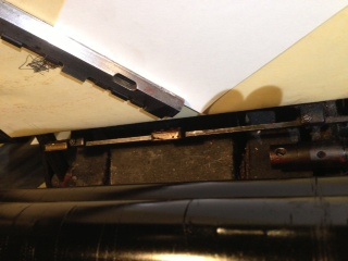
I am the proud owner of two Heidelberg Windmills, the most recent of which was picked up very inexpensively — 1955 vintage. In trying to get this machine to register (for the first time in who knows how long) I’ve encountered a registration problem that has me stumped. Before going on, I should note that this machine was in a pretty serious accident at one point and the flywheel side roller arm has been welded (see photo).
The entire gripper assembly seems to be running late (out of time). It is almost as if the big cam at the end of the crank shaft is oriented incorrectly. First, the gripper arm carries the paper down perfectly, just like my 1967 Windmill. But the guide bar seems sluggish in its rising to meet the paper. When the gripper releases the sheet, the guide bar is still about 1/2” away, and the side guide is nowhere in sight. Then the bar keeps moving up and over (pushing the sheet over the raising side guide). Then, finally, right about at the moment of impression, the bottom guide bar makes its final push up and over, and the side guide punches into the sheet about 1/2” in from the margin. This munches the sheet all around and also leaves a horrible smudge. Needless to say, it doesn’t register either.
The previous owner (under whose watch the accident occurred and who had a local welding shop put the arm back together, regularly used this press for numbering, perforating and die-cutting, and so had no use for the guides.
The following photos chronicle the problem pretty well, I think. The first three photos are before the gripper releases the sheet. Those that follow show where the position of the side guide (about to punch the sheet). Especially telling is the one showing the “ramp” that pushes the bar even further to the right from where it already is. Finally, observe the welding that was done on the roller arm, and the cam that governs the movement and time of the guide assembly. Is it possible that the cam is somehow oriented incorrectly?
Thank you for any suggestions.
1
.jpg)
2
_0.jpg)
photo(3).jpg
.jpg)
photo(5).jpg
.jpg)
photo(10).jpg
.jpg)
photo(8).jpg
.jpg)
photo(9).jpg
had a similar problem with one of my windmills, i run a job every year for 400,000 tickets, right in the middle of the run i noticed the gauges were not rising all the way, the registration was horrible, i oiled the crap out of it and after a while i found out the part that needed oiling was behind the flywheel, the gauges started working and haven’t had a problem since.
Dropped out or forgotten furniture or a free chase that someone laid across the platen during makeready and forgot ?
I would think if you intend to repair this you will need a better than good skill level with engineering tools .
How does the lay bar behave when operated by hand ?
You should see the progression of the two movements ,the side lay finger and the raising head lay you can test that timing by laying down a shet and operating by hand ,the side lay should be up when the headlay has 10mm or so of movement still to go , you can work these things out comparing with the other press .
If you feel its ok then look at the drive link near youtr lay control knob (the bit that locks “on” lays ) compare that with your other machine with the two machines stopped at the same point in the cycle . If this too seems fine i would take the direction of looking at the taper pins being dog legged in either the drive end of the lay assembly or if the timing of the headlay varies from that of the side lay then the taper pin in the Cam casting or the follower castings taper pin . I have found this a problem on three or four machine that have had a chase ingress and your roller arms point directly at that .
you think the both gripper arms and the carrier are in the correct orientation , other than visuals you cant do a lot yourself but check both grippers are ok, a look over is a start ,then open the grippers hy hand ,at the same time watch the ali arm you dont want to see any movement in that arm other than the thing opens and shuts , if you see movement this is caused by the steel hinge pin being bent
repair or replacement of the arm would normally be the best option if they are distorting or binding , discretion obviously because minute movement is harmless .
I doubt if your problem is incurable it is very likely a pin or two have bent in their holes they only have to move a whisker to make things go horribly wrong .
Thank you, all (especially you Peter) for your thorough and somewhat encouraging post. I have re-examined the operation of the entire registration assembly and it basically seems to be operating as intended; meaning, lubrication does not seem to be the issue. Also, the timing of the side guide rising does in fact precede the final rise of the lay bar by about a centimeter. So, check on that front.
The bottom line is that the final push to the right occurs during impression, not before, as is the case with my newer machine. My attention is continually drawn to the position of cam T514 (“Cam with eccentric pin 510”) which sits beyond the left end of the crankshaft, and the small roller on that end of the Double Lever, which rocks back and forth as determined by the cam and the spring that pushes up from the bottom. If this cam could be compared to a kidney, the dent or crook in the kidney on my newer machine receives the little roller right after impression, as the rollers are just starting their trek back down. In that proper motion, the dent speeds the guides down and out of the way as the arm is grabbing the sheet and sweeping it away. On the problem machine, the dent takes the little roller a little earlier, right when during impression when the sudden sweep to the right occurs, and also when the guide cycle reaches its ill-timed zenith.
The Cam is attached to the main gear wheel by a cast bracket with two hex bolts, and then a short, fat rod simply identified in the manual as T 0503 (SEE PHOTO). It seems like this rod may have a doglegged pin, or perhaps has rotated within its seat in the main gear wheel ??? This stuff is hard to see with the flywheel and guards on. I would hate to take this all apart if this hypothesis seems unlikely to you experts. Two things I’d very much like to know are (a) what does a compromised taper pin look like from the outside (the pin where the rod connects to the cast bracket looks fine from the outside), and (b) how does the rod mount to the main gear wheel and is this a potential weak point?
Peter, I was a little stumped by this sentence of yours, on the grounds that my vocabulary is limited:
” … i would take the direction of looking at the taper pins being dog legged in either the drive end of the lay assembly or if the timing of the headlay varies from that of the side lay then the taper pin in the Cam casting or the follower castings taper pin.”
So are we talking about the same basic area? Also, if you were working on this press, would you take the flywheel and clutch off to get at these parts, or would you work around them? Thanks again for your valuable perspectives.
photo-1.JPG
I will sit with the book and list you the parts to look at , the problem will likely be a bent pin but the location is any guess , if the grippers are not situated correctly in relation to the platen closing can also cause the sheet to drop in the wrong place ,
Taper pins can not be seen to be dog legged , you have to locate any that are on affected shafts or those relevent areas .
It is difficult to work out quite what you have wrong without actually seeing it happen but i will keep re reading till the lamp comes on !!!
I have just had a thought , close the platen and see if the gripperarm is sitting not quite upright . (when viewed from front, operator position)
There is a small sprung anti reverse / positioning pawl , if the adjusting bolt is bent the grippers will sit slightly less than upright when the platen is closed ,are you seeing that ? You wont be able to see anything but the out of line gripper that will be pointing up ,The bolt is beneath the gripper assembly shell , but keep out unless the problem is a gripper leans off upright The bolt is T1412- shows on illustration opposite page 85 in part book , if the gripper looks wrong remove the head shell care of spacers and spring must be taken. if the adjuster is bent change it ,its eccentric and you set it so it holds the grippers upright , it may be siezed if you are lucky !!
Thanks! There is a miniscule case to be made that the grippers are cocked ever-so-slightly to the right:
1) When I place a level on top gripper sticking straight up, the bubble floats barely to the left, indicating a rightward (clockwise) tilt
2) Initially, the bottom-most gripper (only one, not the other) scratched the tympan packing and even reacted to the platen when it would open, causing the entire arm to bump up a little. I solved this problem by horsing (pulling) on the arm a little, essentially bending it out of the way. Part of how I justified doing this was that the other arm did not rub accordingly.
3) When the sucker bar sucks paper up, the arm tends to gobble a lot more than on my working machine. Whereas the other machine bites about 1/16 of an inch, the non-functioning machine gets about 1/8, partly blocking the hole that the side guide is going to come through.
I will snoop out the anti-reverse pawl and learn what I can. I confirmed today that the cam does INDEED seem to be in a different location than on the other machine (i.e. the big dent in the cam is what is facilitating the fast, rightward sweep of the lay bar), but I’m intrigued by this gripper assembly possibility. Can the whole thing be off by one tooth?
No it is not going to jump gears , such an occurrence in the head will be pretty terminal as they are huge teeth and the head would explode first id guess.
The amount of material at the pick up is a good point , i assumed you looked at that already , Have you checked that the previous owner has not put shims beneath the front feed board (the bit with blower holes in it ) .
No shims.
I can’t seem to ID the anti-reverse pall. This is up in or around the gear head? Is this the big spring-loaded rod that helps govern when the gripers will rotate to one of their 4 positions? I have an extra gripper mechanism off press that I can study for a better understanding … not that that makes it a whole lot easier to understand.
If you look on the outside of the shell at the top side there is a pair of nuts with a screwdriver fittingslot in the centre thats the tip of a bolt screwed upward frm beneath its not a true bolt as it has a head like a top hat and its eccentric ,
OK, I’ve found T1412, and am trying to ascertain its function and how to adjust it. I guess I’m removing the shell, if I decide to proceed.
Its function is to set the arm in the right upright orientation in as much that it is set on an eccentric shaft with a dog that when the nuts are loosed off you turn the screw a little and the eccentric shaft of the bolt bears the pawl against a shoulder in the ring that is set against the orientation of your grippers arm .
Here is a photo of what I found (after digging through a bunch of ugly white grease; I guess the factory-recommended lubricants are just too much hassle to acquire).
Looks to me like it may not be settling down as much as intended. I peered through the lube hole on my other press, and it seemed to have a better connection. So you think I should fiddle with the tightness of this little screw, eh? Here I go.
pall.jpg
I can already see the dog is shot , can you ascertain if the bolt is bent ? The pawl (dog ) should not have that notch in the tip so that should be replaced as the wear i can see will be a difference of at least 4mins at the gripper tip and if the bolt is bent you have found part of your trouble .
O gosh dang yes that thing is bent! In a second I’ll show you another photo of where the dog goes if the bolt is rotated a bit. I can’t see the notch you are speaking of though.
When I turn the screw a bit, the dog goes here. But can this explain the strange position (apparently) of that big cam that is directing the movement of the guides?
pall2.jpg
Phone whittenberg and order the lot nuts bolt pawl (dog)and i think if memory serves theres a hair spring ,you dont pack this part with grease as the spring is fine and the grease slows its action too much. look at the bit where the ring rests on the dog and in your picture i think its got wear at the point they meet ,the pawl/dog should be flat on the end with a definate sharp edge but yours appears to have a sixteenth lip but admittedly it could be that bulldozer grease thats all over it .
Here is a better snap of the tip of the dog. I am optimistic it is OK, but will inquire as to the price. Could any old flat-head or elevator bolt/screw work for this particular task if the right size, or must I go to Heidelberg … assuming the dog is not worn?
Any thoughts on the position of the cam at the crankshaft?
I am trying to delete a photo of me that I accidentally grabbed from this post. Delete function doesn’t seem to be working. Please ignore my mug if it makes it through.
pall3.jpg
It didn’t make it through. In any case, I don’t see much, if any, wear on the tip of this pall. Your thoughts on the bolt question? Heidelberg or nothing?
Stick to a process of elimination or you will go mad .
The paper starts at the feeder and is picked up by your gripper arms fed through to the lay and so on . Were i able to stand in front of the machine i would be able to tell you where to look in twenty fed sheets but i cant so this is the best approach i can think of and regardless of how we get there you will learn a few bits on the way . We got to this point off track ,but if we had not got to the adjuster you will be still struggling later on . If you have the adjuster off the spare head fit it and using the adjuster set the pawl to the middle of what your two pictures show and reaasemble the head unless you are going to clean that muck out of the head and just leave a healthy level of grease on the gears and such but just give the pawl and shaft some thick oil .
All well said, Peter. Thanks again. I didn’t even think about harvesting parts from the spare head. I’ll let you know when I get it all on there and clean out the grease.
It is not just a bolt as you would recognise its special . it has an eccentric action when you turn it no you cant just put any bolt in it . when you turn the bolt you change the positioning of the pawl ,this pawl is preventing the gripper from moving anti clockwise at any time and when adjusted it is pushing the gripper round in a clockwise direction . when the head is rotating the pawl is out of the way and when the gripper is at the print positin or pick up position the gripper will be in the right position because of this wee little part .
Hmm. I’m getting a bit squeamish. Just got the shield off the spare and that bolt seems “bent” too. I’m now thinking that what I initially thought was a bent bolt is actually the “shouldered” aspect you are describing. As far as removing it goes, it doesn’t seem to want to come out easily. I’m also worried about getting that little spring back on. Thoughts?
As for wear on the pawl ,it doesnt look bad but it will not be easy to see it often is only a small indenting at the contact point in the ring . However a little wear at the centre is a mile at the gripper tip , lets see how things go with the scavenging ,i will spend some time tomorrow workink out a way of finding the next possibility . I will have to crawl over my old girl to find what if any of the pins are most likely to be shot as there are a few options and i will look at the parts you suspect ,i dont think you nwill be needing to remove the flywheel or anything like as serious , i hve a uspicion it may be simply a part of the lay mechanism is tight in the horizontal shaft that goes through the upright of the platen shell ,it has a bush thats about 3 inches or so lonng and it likes to be oiled well as its exposed to the air and any surface rust will tighten it up easily if the rusty bit is trying to slide into the bush ,the shear number of linkages make this one of the few silly bits in the platens design .
You put the spring on easily it is as soft as you can get !!
you will fid it tight to remove but it will come out and the spring you tension it up in your hand and replace the bolt while holding the whole lot carefully assembled once you are in location the spring bears against the top of the pawl on one end and pushes against the inside of the head shell at its other . If you are scared as it were then practice on your spare at putting it back together , count yourself lucky to have the chance and opportunity to practice before you get to jump !
Well, I had it all apart and familiarized myself with how these shouldered bolts work. Okay, I didn’t remove the bolt, and put the shield back on before seeing your most recent post. The thing is, both bolts on both units worked identically to one another, and in both cases could be rotated (even with the shield on) to set the dog deeper or shallower. I figured I had that all figured out at a certain point, and so I experimented with different depths before coming to the conclusion that it didn’t really matter where it was. Sheets fed into the press exactly the same as before with the same crunchy result. That said, this gripper assembly exploration was valuable in that it showed me how this bit of the press works. I wish you were here to agree (or not) with my preliminary elimination of the dog as the problem. No matter where I had it — shallow or deep — the sheets munched all the same.
Thanks for being willing to take a look at your press tomorrow. I can pretty clearly see the two points of tension in the guides linkage. The big boss is the spring pushing up from the bottom (T0455). He pushes on one side of the double lever (T0450), which causes the other side to bear down on the big cam (T0514F — do older machines not have the F?, perhaps this part has changed since the 50s?). This cam just looks to be oriented differently from the working machine, and since it doesn’t look broken or cracked, and the two hex bolts are aligned with one another and screwed in tight, that has got me looking at the big fat rod (T0503) and the cast piece (T0509).
On the other end, you just have the spring on the right hand side of the platen that keeps the rod you mention from hanging around to the right for too long. When I pull the little knob out and to lock out the guides, that little spring pushes it all right on over and down, no problem or sticking at all.
Ok i will look in the morning and see if i can see something is likely to be causing this , i assume you have the correct set up on your pile position in relation to your lay gauges pile fully to the leftfor brass gauges .
I am hoping for your sake you dont have to get in there and have to drill .
Seeing as you have noticed the grippers were bent to the platen do you have a good evenness in the height off the platen surface along the gripper length and do both grippers stand off similarly from the platen ?
Pick up a sheet in the gripper and stop the platen and take a line along the gripper edge with a felt tip onto the sheet .
open the gripper and mark ithe sheet and mark the gripper. put the sheet to teh side and take another sheet up in the other gripper stop it before it shuts and mark that sheet along the gripper edge .
check to see if they are first ,square and second if they are holding the same amount , 1/4 will do for the time being , what do we get from that.
T0454 the bit that pushes up wards with a spring (oilT0450) oil the fulcrum point liberally as the spring has to work pretty hard in there and all sorts of dried crap gunks that up . You will probably find the oil hole buried in gunk.
Thanks again, Peter. I will lube it all up again and see if it acts differently. I also thought of a way to check the position of the cam and shaft — free them up from the roller and linkage, then give it a crank with a big wrench and see if it moves. If it does, that should tell me if the taper pin is busted or if the shaft is moving in the main gear. Today I went and checked out another (older) press in my area, 40s vintage, which seemed to confirm my finding that the cam is improperly oriented.
How neat does the weld look in relation to the shape of the casting ? You may see if the weld is not positioned right , yes the removal of linkage to find a moving casting at the drive makes sense , the problem with dog legged pins is these are so well machined everything fits a bit too well !!
Crawling over mine is no problem I currently have a part to replace on the other side of the machine from you ,embarrassingly i have to admit to a bit of neglect !
Well, here’s a small development. I just gave the big taper pin a few taps to see how much persuasion it would need in order to move. It was quite agreeable, and started to budge after just a few moderate taps with a 3 lb hammer and punch. I cycled the press and tapped it back in from the other side, so that was an easy test. I’m thinking that if it was bent it would have put up more of a fight. So either the shaft is rotated on the side of the main gear, or the problem is not with the cam after all, but some other spot in the linkage, which is perhaps causing the roller to hit the cam in a strange place. I have also re-evaluated the fulcrum (good shot of oil) and have to conclude there is nothing amiss in terms of lubrication. The springs on both ends are having impressive effect in determining the position of the guides linkage.
The weld looks fine with one exception: It is carved out where the cam passes through. (See Photo)
weldgrinding.jpg
if you lean over the plten and manually operate the front lays Look to page 30 /31 at part no0230 without bothering to check exactly with mine , take a look at the pins in and around this part as well as the flat linkage that goes back to the drive cams ,that linkage could have bent ,it has a deliberate kink at either end but should all the same be straight between the bends at either end .
Theres always a chance of a fix if you cant find it just change the length of the llink but if its a pin it will come back to haunt so keep looking .
How much play is there in the Lock mechanism that is part 0232 into 0231, If the hole in 0231 is too elongated with wear or the pin through that hole is bent you will have lost some of the movement in the play ,
No dice on any of this, Peter. I too thought of lengthening the linkage from the double lever to the lock mechanism, but that thing is exactly the length it is supposed to be right now. I can also see that the nooks and crannies in the cam are intended for certain things in the progression of the guides. No, I am now all but certain, something has rotated that cam, probably by rotating the aforementioned shaft (T0503) within the main gear ?? (T0502). I have to imagine it happened when the arm broke, or shortly thereafter before the welder ground it out to accommodate the cam (collision on post-repair maiden voyage). I just can not see any other possibility from where I am sitting. Thank you, sincerely, for your insights and attempts to solve this very vexing problem, but I am going to have to explore the possibility of drilling the shaft, removing the flywheel and main gear, or both! I hate to utter the words “parts press,” but I’m looking at that possibility too.
Before you consign it to death ,which to be honest would be daft seeing as there are companys who refurbish the dead , have a look at the pins in parts T0214 and T0230 /31 .
Although having looked again at mine with the manual and your pics to hand i think that linkage would have to be lengthened , the reason can only be as you suggested repeatedly the drive assembly has moved somewhere ,i cant see the gear moving on the shaft it has keyways/woodruff locks , they dont slip without the casting breaks . It is possible during repair someone didnt put the key in on re assembly ,or the Welded part is rotated enough to whack the time out .
How does it run on fixed grip as i know it ,that is with the gripper release cam set closest to you so the machine holds the sheet all through the cycle ?
I ask that just to see if you have during your test not overlooked setting the cam for sheet release ,you wouldnt be the first and i have done it a few times .