disc lever stud for a C&P
I am looking for a disc lever stud for a C&P 12’x18” NS.
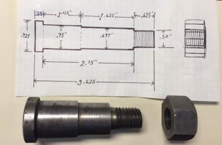
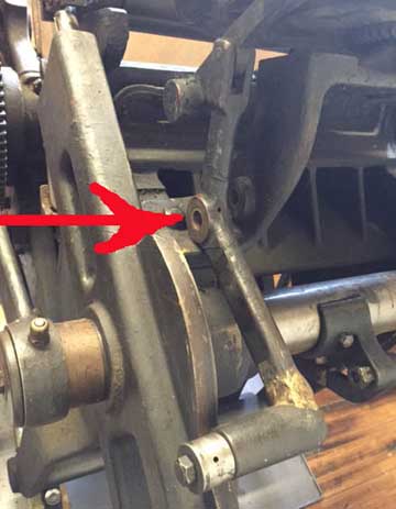
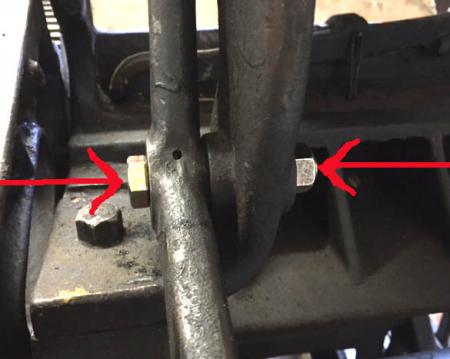
The attached pictures show the part and location on press
A drawing of the dimensions is also shown.
This stud holds the ink disc lever in place and allows it to rock back and forth and turn the ink disc.
If anyone has a spare one please get ahold of me.
Thank you all in advance for any assistance.
Jon Drew/Mpls
612.270.6449
[email protected]
1.jpg
3.jpg
4.jpg
Should be a *doddle* for a first year/first grade engineering student, probably as an *Apprentice Piece* to manufacture a replica.
Here in the U.K. just for speed we would merely source an ALLEN BOLT with the Shank at exactly the correct bore/size, i.e. your .75” the shoulder turned down to your, 1.625” x .697” threaded in the lathe to accept (probably) imperial nut with built in Self locking (Nyloc or similar) system-no need for locking washer??
The Allen Bolt head left as is, rather than screw driver slot.!!
Allen bolts here come in High Tensile steel or Stainless both machinable for turning and threading, even if the thread is run on by hand whilst still gripped in the lathe-this would be one of the first lessons, prior to lead screw threading on even a simple lathe.
Our Thompson British Auto Platen,s (similar to H/bergs) are alive with just such 2 stage Bolts so rather than source new stock, we would and have merely turned one down to suit.!!
At the absolute Max. less than $2 electricity, less than $3 for stock, Machinable or Stainless, Maybe $5 for an Allen Bolt, no more than 1 hour, total time.???
Good idea Mick, and here is a shoulder screw which I think should work, if I have read all the dimensions correctly……3/4 dia. X 2 3/4 shoulder.
http://www.mcmaster.com/#shoulder-bolts/=xyxqf9
At the left side of the McMaster-Carr screen, check 3/4 shoulder diameter, then 2 3/4 shoulder length, then steel for the material.
The thread of the screw they have is 5/8 (.625) instead of your 1/2 on the drawing, but that should be OK since it is less than the .697 diameter of the smaller shoulder.
You just have to get the .697 part turned down.
BUT WAIT A MINUTE! Comparing your drawing with the part underneath it, it doesn’t look like the drawing matches the part. The .697 shoulder looks to be shorter on the part than it is shown on the drawing.
Yes, did notice that the schematic line drawing (which was precise and informative) was not compatible with the actual representation, (also clear and precise) but assumed that, that was to illustrate the Modus Operandi, required.
With such precise and accurate details regarding dimensions, a replica/repro would be a doddle, if an off the shelf was NOT available.
One more gimmick if all else fails, (we have several times in the past) acquire a standard bolt of adequate length with the shank, parallel along its length and have a simple collar machined to accomodate the larger dimension .75” etc.
Machined from Brass, Bronze, Oil-lite, with the added advantage of (the collar/bush) acting as a bearing surface, probably better than original, >>i.e. High Tensile Steel running in Cast Material and probably no Oil hole.!!<<
Technology has moved on since those days. Good Luck.
That’s another good point, Mick, about the material. As you imply, machine designers generally specify that the easier-to-replace and cheaper parts be made out of softer material, so that they will wear instead of the harder-to-replace parts which they are mated to.
Some people think to themselves: “that part is worn so I will make it out of a harder material so it won’t wear again.” That is exactly the wrong thing to do, because something has to wear, and then the harder-to replace parts will wear and give the owner a much bigger problem.
Geoffrey, Thank you for elaborating on my humble efforts re using 2 dis-similar metals, where one is to be regarded as *Sacrificial*
Your *that part is worn etc.* is spot on, but is a fairly understandable conclusion to arrive at, especially by the New Kid on the block, wrestling with the learning curve ahead.
I am grateful and count myself fortunate in that in the late 50,s (along with many others) on one of several visits to the Monotype Works & Factory in Redhill U.K. was shown the results of terrible wear on hard steel shafts running in equally hard cast bearing housings. . Including serious lack of oil.!!
This aspect was made abundantly clear in their (Mono.s) Black Museum, designed to bring home the message to Know All,s like *the Author* for example. .
By way of explaining my appreciation of bearing bushes etc.and lack of oil holes.!!
You guys are the best.
MoM was right, after reading both of responses it is so simple, definitely a ‘doddle”
Geoffrey’s McMaster suggestion was right on. That bolt will do the trick.
You both were quick to notice that the part pictured did not match my drawing. Well if it did then why would I post after all.
I neglected to mention that the part was from a smaller 10” x 15” C&P
All the best from Minneapolis.
JD.
J D. thank you, not quite that simple but neither is it the Rocket Science that your **experts** would have you believe and charge accordingly for.???
Again top marks for the schematic,s etc, always make life easier for would be advisers,? as witness Geoffrey,s input.
There is (we believe) a fairly famous quote, maybe Limey rather than Yankee, something like *Give us the tools, and we will do the job* Good Luck. Mick.
JD, thanks for your last post. It is always nice to hear that the time we take to make suggestions, etc., is helpful and appreciated.
This is a classic example of the fact that groups can solve problems better than individuals. I wouldn’t have thought of using a shoulder screw if Mick hadn’t brought it up. Thanks Mick, for that and for all the other wonderful suggestions you have made over the years!