Vandercook 232P Gearbox Problem(s) and Why not an AC Servo?
Hi everyone!
A longtime lurker, first time poster. I am going to throw at you a serious problem… :)
So I’m having an issue with the main gear box assembly of 232P
Metal to metal grinding sound (NOT FROM THE GEAR BOX).
Originally, I had assumed a gasket started to leak ( the oil level inside the main gearbox assembly was reduced more so than usual one day). But with a subsequent refilling, the level remained normal after several runs. So I started to think it’s the clutch.
The way the press was struggling to move also indicated (I think?) the clutch slippage(?).
On the day I thought the gasket leaked, I also, for the first time, injected some general purpose grease via the grease nipple (shown green) - I’ve never seen that grease nipple till then. And for whatever reason, the excess grease inside the shaft appeared to have spilled into the center of the clutch assembly (shown cyan) and introduced grease to the clutch pad.
The problem appeared to have subsided after some “okay” cleaning of the pressure and friction plates with acetone but the more I dug in, it appears there is a massive issue with the main gear assembly (area in yellow).
The pressure plate(2) begins to rub against the base of the gearbox assembly frame (shown magenta) as a new “give” is being introduced after a certain rotation of the plate. Even w/o the normal tension from the pressing friction plate, the pressure plate appeared to just cave in towards the main gearbox assembly.
Now, I like to dig in to the problem further by examining the area of the gear box (3) but I just can’t figure out how to remove the friction plate assembly (7) from the press frame.
Initially I thought removing the brake pad (just below the pressure plate) would give enough space to allow the arm to pivot enough counter clockwise (pivoting centered at 6) so that the curved plate that goes through the friction plate shaft would clear it so that the belt pulley (7) can meet the press frame. But one of the two prongs (rear) that holds the break pad would touch the base of the gear assembly…
I like to get a full access to the pressure plate (2) so I can remove it and mess around with (3).
The pressure plate is held by 6 flat (-) screws that the some clearance I could achieve between (1) and (2) by moving the shaft towards the front of the press (left in the diagram) is not enough.
ANY IDEAS?
ALSO:
I’ve been thinking about either removing the tension pulley drivetrain system all tougher and outfitting the press with an AC servo motor power instead…
… Or leave that intact and attach an AC servo motor powertrain in addition to - not to be used simultaneously…
I like this idea for the following reasons:
1) less noise - motor only running when the cylinder is moving
2) additional sensors for safety.
3) should be able to stop the cylinder when encountering non-normal operational pressure
4) should be able to move the cylinder fwd and back w/o having to have the belt driven motor to come to a complete stop
5) should be able to tuck the entire drivetrain under the press bed.
6) gradual acceleration and deceleration with perhaps faster cylinder movement overall
7) exact placement of the cylinder, at the start and at the end.
I have no idea how the Automask assembly works nor it’s installed right now but (7) may provide a benefit…
Any thoughts?
Thank You!!!
T.Y.
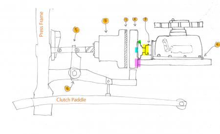
vandercook 232p powertrain.jpg
Attached below is the photo of the area. The break pad is still installed in then photo. The magenta area is the region of contact:
Thank You!!!
IMG_0956-2.jpg
I don’t have any hands-on experience with this model but know that Martin Mazorra in CT and MICA in Baltimore have these too. You might want to post this over on the Vanderblog or write directly to some other 232P owners.
DGM
Here is a link to the video of hand turning the pressure plate. You can see no resistance for a few turns then it comes to a screeching halt as it moves closer to the gearbox assembly and begins to touch the base of it:
https://tinyurl.com/vandercook-232p-gearbox-issue
Thank you Daniel!
Art Center College of Design has one of these too and they would be much closer for me for a visit. Lemme post to Vanderblog now.
THANK YOU!
I work on one of these down at Hatch Show Print as well, though it seems to have a slightly different assembly for the whole system as our belt rotates around the belt pulley parallel to the floor, so our clutch assembly is a vertical motion. I’m curious to find out your solution to the problem to know for future reference.
On another note, I just repaired an automask assembly on a 28-42, which is essentially the same as the 232-P, so if you want to get that going, I can lend my knowledge.
Cory
If the following is a complete *red herring* apologies, but it may just help to understand or isolate, the problem.
E.G. look up on the web, >Worm Gear/Worm drive, schematic diagram(s)< in essence that is what You have.
It is a strange animal, the schematic may help to work out why You have the partial rotation, ONLY.!
Apologies again for possible rubbish
So I couldn’t post to Vanderblog for now because it appears that the new user registration link points to nothing, a 404 error…
Worm Gear. Yes. It is… Must be…
I can’t even get there yet, unless I remove the clutch assembly first (I have no idea how to remove (6) from the 1st diagram) or the main gearbox… Which involves removing the chain… and so on…. This feels like when I was fixing an old house from the late 1800s… More and more parts of the house had to come out… And I know things just enough to be dangerous…. :)
https://TinyURL.com/vandercook-232p-New-Powertrain
So I was thinking I would use one of these (power spec TBD) mounted somewhere beneath the press to drive the press instead of fixing this like it was, but still using the existing gearbox (means I would need to fix it)…
But I think I can just make two holes on the left side of the press to pull thru’ a chain from the servo to the chain gear with appropriate reduction ratio (TBD)… (a new box, so to speak, which will house the existing sprocket for the cylinder drive chain with a larger-than-the-servo-sprocket sitting directly beneath it in the same shaft. Then the whole assembly will be greatly simplified. Keeping the motor outside will avoid lubricants from the press to contaminate the servo.
Kind’a excited about this but the unknown is a bit scarring me from starting it…
The rough diagram below is the top view of the press with the see-thru’ press bed showing the cylinder drive chain and the location for the new AC Servo and the chain connecting to the main chain sprocket shaft… Once I get to the shop Monday, tomorrow, I’m going to spec some requirement and see if this is possible.
If creating holes or a slit on the press wall doesn’t look too good, I suppose I could still house the servo underneath where the clutch assembly is at the moment…
I think I’m posting this here for a moral support as much as some technical input :)
ps: Cory, YES! I would love to chat with you about this automask assembly. I’m even thinking I can add another, but much smaller ac servo to drive this mechanically independent from the cylinder movement (w/o the chain) too…( not that this would necessarily be a wiser solution)
AC Servo location:
ac servo plan.jpg
Existing Drivetrain:
ExistingSetup.jpg
Taro,
Send me an e-mail through Briar and I can lend my knowledge on the automask assembly, I also have a PDF of a 232-P manual if you need that for any reference.
I misspoke before, and I actually repaired the system for the auto cylinder on a 28-42, referenced as the “Cylinder Control Lever” in the manual, all the springs and bars near the floor on the operator side. I did actually repair the whole frisket on our 232-P however, so I can still lend what I know, and some insight on the possibility of attaching a servo to that system as well.
Cory
OK!
Removed the main cylinder chain. The worm gearbox has also been removed.
The free moving cylinder makes me a bit sad… A limp and dead press.
BUT!
The problem has been isolated!! The pressure plate that was collapsing towards the gearbox was being caused by the end “screw(?)” holding the non-shaft end of the worm’s bearing in place (see pictures below). DUH! But now I know!
This also explains the leaky lubricant.
It’s all taken apart so I may as well slap on an AC servo motor (see a new diagram below). I may even paint the gearbox!
Will keep updating on the servo motor transition.
THANKS EVERYONE!
worm drive issue found.jpg
The new position and the scheme for the AC servo:
New Direct Drive Scheme.jpg
UPDATES:
Happy Holidays!
After a long long delay, from general difficulties, a steep learning curve, cost over-runs and multiple design changes (OH EXCUSES!!!), we’ve settled on the last design as shown above.
The existing worm-angle-reducer-gearbox will be turned 90° CW from the original position to accept the new servo motor (also turned 90° CCW from the original induction motor position). The new angle reducer would’ve been HOT with pretty much no bear-backlash but it wouldn’t have fit physically (beneath the press) and blown our budget …
We’ve done a proof-of-concept run, so to speak, with a super tiny servo motor, that takes the equivalent input (and signal output, but we are not there to deal with that yet).
Look how cute this little one is compared to the final 1000W version: (the AAA battery for scale)
Also pictured after that is a basic proof-of-concept servo-controller:
————————————
We have two big hurdles going forward:
1) Turn and bolt (with new bolt holes) the gearbox. The existing arrangement has three bolt holes 120° separated from the center of the gearbox. We will pursue drilling three new holes on the gearbox 90° away from those holes rather than drilling new holes on the press’ gearbox platform.
2) Mount the motor on the motor platform, perfectly aligned to the input shaft of the gearbox (some cutting/drilling of the exiting cast-iron frame of the press is required to pass through the shaft and the coupling) since the input shaft of the gearbox is not centered to the motor platform.
Until the next unsolicited update, please enjoy Hilda’s new red shoes (for her new looks, operator ergonomics and quake safety - California here!!!)
hilda foot.jpg
hilda shoe.jpg
controller.jpg
servos.jpg
Ok, we’ve finally got to the point the press can be run….
More de-brief to come but for the time being, please enjoy this short clip:
https://www.youtube.com/watch?v=R9HeRFWCDmY
THANK YOU!!
Man, these people who post YouTube vides all the time, we have a new found appreciation!
We’ve posted a longer video of the new setup, focusing more on magnetic sensors.
https://youtu.be/YOnBMLhRatI
There are three LED indicators. Orange, Green and Red. Orange is for power. 3.3V. Green is on at all times when there is power (more on this later). Red is only on in a presence with a magnet.
We’ve mulled over what cable and connectors to use but at the end, we settled on a standard CAT-5 network cable (stranded) and RJ-45 sockets. These are easy to crimp and easy to get.
When a magnet is present, the optocoupler associated with the red LED will open, yielding in HIGH output from the perspective of the main controller.
In order to make sure that in the event of the sensor disconnect, that the sensor will not trigger with the passing magnet, the other output, the Green optocoupler, is designed to output HIGH when connected and without a magnet. It then outputs LOW when a magnet is present. The LED stays turned on and that is our design error :)
So, when comparing the two output, Green OR Red should always yield HIGH - this is our simple algorithm for detecting a disconnect. That is to say, if the result of OR operation is 0 (Green is off, and Red off), we can assume that the sensor has come loose. BTW, this triggers an emergency stop operation by the controller.
Thanks for watching!!!
The CAD render animation is uploaded now. This is the piece that joins the servo to the press. Specifically, it gets mounted on the side of the worm-gearbox base of the press.
The worm-gearbox was turned 180° from the original position to be pointing directly to the servo’s shaft.
The whole piece is created using laser cut 5/8” mild steel, welded to pretty tight tolerance using tabs and notches that were designed into the individual pieces. They were all tack welded first before the final weld.
Here is the video on YouTube:
https://youtu.be/fVo5URlwLQA
Thanks for watching!!
OH MY this took a long time.
HILDA is finally operational:
https://youtu.be/3Rk5J0hQGaE
But we have so much more we want to do with the system. Please stay tuned and thanks again!
Screenshot 2019-09-24 21.07.02.jpg