Motor Mount
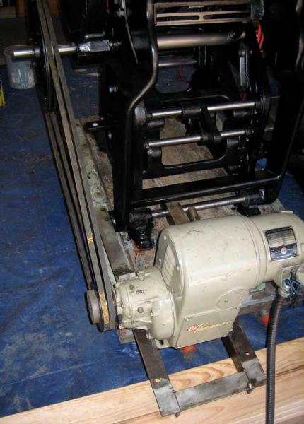
Can anyone comment on how this motor mount should be positioned and attached to this press? It came with my press (C&P 10x15 NS) but was not attached.
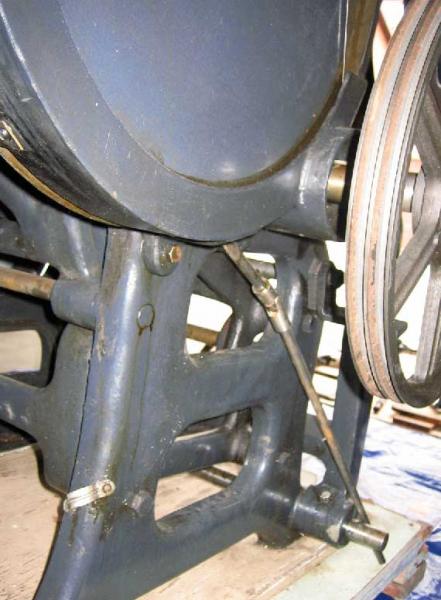
The motor is a variable speed and the control arm (see pic6) needs to connect into the front of the motor.
I’ve attached pics of my guess for how it might work but thought I’d ask the experts here.
Thanks for any assistance.
Joshua
Picture3.jpg
Picture5.jpg
Picture4.jpg
Picture6.jpg
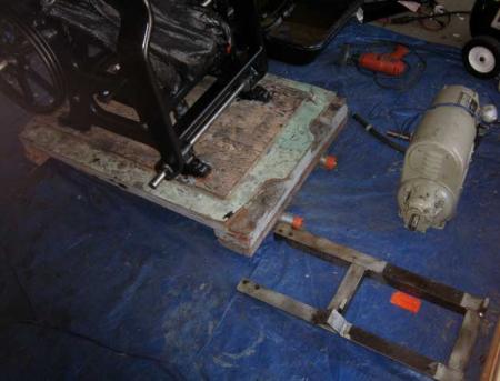
It looks like you generally have the right idea in your first photo. However, these type of mounts, homemade as this one or otherwise, worked in such a way that the weight of the motor kept tension on the belt.
It looks like a wood or metal plate was mounted to the motor mount with the four holes in the mount and that the motor was actually bolted to that, farther back than you have it in the photo. Cut a piece of 3/4” plywood or solid stock and bolt it to the mount using those holes, then bolt the motor to that. You may want to cut slots in that board to allow for some adjustment. Keep the motor back farther towards the end of the bracket. This will cause the bracket to have to pivet up on the shaft, bringing the motor and therefore the pulleys closer together in order for the belts to go around both pulleys. The motor and mount will then be suspended by the belts and the belts tensioned.
That should also allow the speed adjustment rod to be connected since I’m assuming this setup was used before. One thing you may want to do and I’d recommend is to buy a locking collar that will fit over the outside of the motor mount shaft and up against the mount where the shaft goes through it. This, combined with the bed casting on the other side of the mount, will prevent it from moving left or right on the shaft and keep the belt alligned with both pulleys. A washer and cotter pin would work also though you’d need to drill a hole in the shaft for the pin.
Rich
Front Room Press
Milford, NJ
http://frontroompress.com
http://frontroompress.blogspot.com
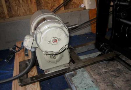
Something I didn’t mention before so as not to confuse the issue is that factory-made mounts of this type had a threaded rod that connected the mounting bracket with the side of the press. This allowed the belt tension to be controlled as well as keeping the entire mountring system stiff.
After looking again at the photos I see that whoever made this bracket allowed for that also so I’d better explain. On the outside arm of the mounting bracket you can see an angled bracket welded on the top side. This will have a hole in it on the front side. On the side of the leg of the press is an angle bracket with a hole in it.
Buy a length of threaded rod of the largest diameter that will fit in the holes, along with four washers and four nuts for it. After you get the motor mounted and the belts on run the rod through the leg bracket and down into the hole in the bracket on the motor mount. Leaving some extra legth for adjustment, mark the rod to the actual length needed and then remove it and cut it.
Place a washer and nut on one end of the rod a few inches from the end and a washer and nut on the other end of the rod perhaps 6 inches or so from that end. Place the end of the rod with the washer and nut 6 inches from the end up through the bottom of the leg bracket. Place the other end of the rod through the hole in the bracket on the mount and put another washer and nut on that end. Tighten the nuts so the rod is firmly attached to the bracket on the motor mount.
Place the last washer and nut on the top end of the rod coming out of the leg bracket. Screw that nut down until the full weight of the motor is taken off the belts but there is still reasonable tension. Then screw the nut on the inside of the rod at that end up tight.
This is a better setup and will prolong the life of the motor bearings and belt and will lessen any vibration. Whoeevr made that mount did a good job.
Rich
Front Room Press
Milford, NJ
http://frontroompress.com
http://frontroompress.blogspot.com
Wow, Rich. Thanks so much for your incredibly detailed comments. They make complete sense and I will configure this just as you described. I’m not sure how I could have done this restoration without your (and others) help!
Great tips for the collar or washer/pin on the shaft to keep the mount in place. I’d prefer to not have to remove the shaft from the press to get a collar on but can if I need to. Also, the threaded rod/washer/nut solution from press to mount sounds great. I figured there was a reason for all of those extra bells and whistles on the mount!
Does anyone have a picture of this kind of motor mount configuration? If not, this seems pretty straightforward thanks to Rich’s thorough explanation.
This motor is a three-phase motor so I’ll first need to convert our electricity from single-phase. Look into phase converters, etc. I want to confirm that this motor works first before I configure the mount for it (the previous owner assured me it runs). Does anyone have any recommendations for converting from single to three-phase? I’ll probably get an electrician in to take care of that and configure overhead lights, etc.
Thanks again, Rich. I’ll keep you posted on my progress.
Joshua
You should only need the collar on the outside of the shaft. The collar and the base of the bed casting will capture the outside arm of the mount between them and keep it from moving. These collars are a couple bucks and if nothing local is available call McMaster-Carr. There are several kinds available, just get the simplest with an Allen set screw.
Take the motor to a local electrical repair shop and ask them to test it for you. The best phase converter is a rotary model as it puts out more power but it is also the most expensive. One for a 5 hp motor can cost $800. Static/electronic converters are available and for a press with a low horsepower motor it should be more than adequate.
Converters never allow motors to put out their full power but rotary ones come the closest to 100%. But again, the expense isn’t necessary in this case. Remember to get one rated for more than the horsepower of your motor. The electrical repair shop will likely have some suggestions.
If your motor wasn’t variable speed I’d say don’t use it and buy a used single phase. But the variable speed has value and you should be able to get a converter for between $100-200.
Rich
Front Room Press
Milford, NJ
http://frontroompress.com
http://frontroompress.blogspot.com
Thanks, Rich. I’ll pick up a collar from McMaster. That will work perfectly!
Great tips on the motor and converter. This is a big help as I was struggling with which would be a better, more cost effective solution - converting the existing motor or buying a new, single-phase. Need the variable speed controller though. Nice to hear that this could cost less than I originally thought.
Thanks again.
While this discussion is about a motor mounting I have an add on question of a slightly larger scope (I’m working on rebuilding a press): Is it more desirable to have a belt drive, rather than a geardrive so that the press can be advanced by hand via the flywheel?
I’d value your opinions.
On the converter side, the modern solution for that is a VFD (Variable Frequency Drive). You can buy them with single phase input and three phase output in a great variety of voltages.
Hugo
In my opinion at least, it’s essential that you be able to easily turn the press over by hand. There are a number of reasons for this. One is that you want to test your packing to make sure you will not smash the form. You do this by slowly cycling through an impression by hand. You also want to be able to stop the press quickly. Since the flywheel should be turning away from you, this is easily accomplished by cutting the power and grabbing it since it shouldn’t be going very fast anyway. Or a foot brake can be set up and used. Another reason is troubleshooting. You can often get a good idea of what is causing funny noises or where something is going wrong by turning the press over by hand. There are more reasons but you get the idea.
It’s true one can purchase VFD drives, assuming one has the money or a rich uncle. Otherwise, it’s worthwhile using the original motor even if a phase converter is needed. Another good reason to use an older motor made before the 1970’s is that it has more copper and therefore more torgue compared to a similarly sized new motor. Copper became expensive in the 70’s and the amount used in motor windings was reduced. That’s why older motors are generally larger and heavier than new ones of the same horsepower. You should still be able to buy an electronic phase converter and have everything wired for much less than a VFD motor.
A consideration for some is the vintage look. Personally I like the older designs and styles used in machinery and I try to be consistent in my shop with all the tools and equipment I get. That has no bearing on operation but it gives me greater enjoyment.
Rich
Front Room Press
Milford, NJ
http://frontroompress.com
http://frontroompress.blogspot.com
I was kind of guessing that it would be valuable to have the manual flywheel action, and am glad to hear that substantiated. Also it is my guess that a gearmotor would defeat the dynamics of a flywheel. On the old motor front vs new motor I can’t agree. The old motors were overdesigned in thermal capacity to assure they would meet specifications. But they would output no more torque than a modern motor - while admittedly you could overload them longer. A modern motor, specified for inverter duty, has a much better insulation system though. That is what is important if you use an inverter or VFD. VFD’s have become massproduced (they are now used for furnace motors and washing machines), so you no longer need the rich uncle. A couple hundered buck will do. And the benefit is a whole lot of parameters are available that can be set up to protect the motor (ramping speed acceleration/decel., loading, thermal protection - even dynamic braking on some). Of course who would argue about looks, modern control gear positioned on old equipment looks awesome to me…
Hi Rich,
I ended up getting some u-bolts to connect the motor mount to the shaft of the press. There were already holes in the motor mount for the u-bolts so that worked nicely.
I also configured a threaded bolt from press to motor mount (with nuts on each end) per your instruction. That seems to be a nice fit and will work well.
I am now trying to position the motor on the motor mount so that aligns properly with the variable speed control arm/shaft the continues up to the front of the press.
I’m trying to determine the correct path/position for the speed control arm to go “through” the press from front to back. It needs to enter the motor perpendicularly and in a position that allows the pulley on the motor to align with the pulley on the flywheel shaft. I also need to mount the handle/plate at the front of the speed control arm to the front of the press.
Do you have any ideas or tips on how or where this arm should travel through the press? I’ve yet to find a position where everything lines up correctly. I am unable to move the pulley on the flywheel shaft further away from the press as there is some kind of piece attached to the shaft that catches/locks the pulley to the shaft (see pin.jpg). Because of this, I can’t move the motor/pulley away from the press either. Can this pin be repositioned on the shaft?
Should the speed control arm go on the inside or the outside of the bed leg? Also, should the base of the motor be parallel with the motor mount or does it need to be angled up (as seen in pictures)? Not sure what area this arm should pass through and nothing seems to work correctly - yet.
The image original.jpg is the original position of the arm. My issue with this is that, in this position, the motor will have to be positioned too far to the right and, therefore, the motor pulley cannot align with the flywheel shaft pulley. Again, unless I can move the round “pin” that is embedded in the flywheel shaft “under” that pulley.
Thanks for any assistance with this!
Joshua
pin.jpg
original.jpg
front.jpg
inside_over.jpg
Am I seeing things correctly in the last photo that the speed control arm attaches to the back of the motor, not the pulley end? We know that the motor mount was onced used with this press and so were able to figure out how to reinstall it. That might be possible with the control arm if there is any evidence this motor was used with this setup.
The drive pulley on the press is not original to it and that pin is a remaining part of whatever kind of pulley arrangement was on there at one time. So if necessary it would not be the end of the world to remove or file down that pin in order to allow the current pulley to be moved over if necessary.
The control shaft may not need to go through the press at an angle. It can be down lower, perhaps straight forward from the motor. The dial end could be attached to a block of wood mounted on a board attached between the two runners, though I see your press is still on some kind of pallet. If you look at some of my photos you can see how I did something similar with the pedal speed control on my press.
The speed control dial you have doesn’t need to be right at hand when you’re standing at the press. Once you get the speed adjusted your not likely to be changing it much, if ever until over time your ability to feed gets better. I run my press at 14 ipm and doubt I’ll be going faster anytime soon. I like my variable speed motor which came with the but honestly I doubt it’s necessary at all on a hand-feed press. A fixed speed motor was fine on my old 8x12. I just used a countershaft and the correct-sized pulleys to get the speed I wanted.
Anyway, see if there is any place on the press where the control was once mounted. Also, place the motor in a position on the mounting board so the pulleys line up properly. Then see if you can run the control rod strainght out. If not, how far to the left or right would you need to move the motor to be able to do so?
Rich
Front Room Press
Milford, NJ
http://frontroompress.com
http://frontroompress.blogspot.com
Rich
Same speed is okay but I find on some jobs It’s better to slow down if stock is hard to feed or if heavy coverage on foil.Heavy stiff card can be hand fed at about 1500 iph. In general set at a comfortable speed and sell every sheet. Tortoise and the hare.
Mike
Oh, I agree completely. I’m glad my 10x15 came with one to give me the option. I just wouldn’t spend a lot of money (if I had any money) to get one if I didn’t have one.
Rich
Thanks, guys.
Rich, yes, the control arm enters into the back of the motor. I really like the position of the control handle at the front of the press so I think the best and easiest solution will be to move the pin along the flywheel shaft so that the pulleys align properly. I’ll look into my options for this soon.