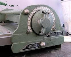
Line-o-scribe adjustment mechanism
Hello all
I’m considering making a flat bed “captive roller” proof press (or adapting an existing base), and would like to make it adjustable.
I’ve been trying to find out how the Line-o-scribe roller height adjustment works, as I’m mystified how it manages to do this while maintaining accurate height above the bed. I can’t find any info online, and can’t find their patent filing (which admittedly is old). I’d also be interested in the Farley, which appears to have a similar mechanism.
Can anyone shed light on this?
Thanks in advance, Chris.
Linoscribe.jpg
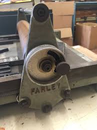
Farley.jpg
I can’t speak to either of those machines, but generally when such adjustments are required for a roller on a shaft, the shaft is attached to the uprights with an off-center eccentric. As the shaft is turned within it’s attachment point, the roller moves up or down relative to the adjacent surface. that method maintains parallelism between the roller and the surface.
Other systems simply the roller on each side, with the potential for getting the roller out of parallel with the surface. That method also will work, but requires more fiddling to get equal distances (like setting inking rollers on most cylinder presses).
John Henry
Hi John
Thanks for your response. But I’m afraid I don’t get it. Surely you’d need an eccentric at each end of the shaft, coupled in some way? I’m probably just being dim here…
Cheers, Chris.
C.C. (Chris) the concept of eccentric cams and shafts, is not an easy one to get Ones head around.!!
Elaborating on J.H.s, comments above, our Farley Proof press,s are virtually identical, in original format to the Lino scribe,! in the pictured shot of the Farley the knurled thumbscrew at bottom right (approx)is the locking device for the adjustments, the much larger ring (slotted) is the actual adjustment for raising and lowering the Cylinder in relation to the Image medium,- there are fine increments marked on the Big ring, aligned against a fixed pointer, to set and reset, either for Type/Image matter straight onto the *Bed*, OR Type/Image matter on a galley, the adjustment increments (per job) usually recorded, on the Job Docket, The Wall, etc.
As J.H. implies the entire Axis/Spindle for the cylinder is ECCENTRIC at both ends, usually turned as one on a LATHE, the bearing surfaces are carried in the side stanchions.
If possible check out, *Camshaft* on Wikipedia, usually the very first entry gives a good overview/breakdown, of the principles of Camshaft,s including a tiny schematic, running live in the corner of the Eccentric principle of the pear shaped *Lobes(s) driving the required part(s) up and down, precisely the same as raising or lowering the printing cylinder on the proof press.???
OR
Maybe (if possible) check out an exploded diagram of the Chandler & Price Press, with particular attention to the Main Gear wheel which carries an elaborate (single) CAM which in effect does the same job as the eccentric(s) on the proof press.
Owned and used, several Farley.s since the Mid 50,s.
My best shot, above, with apologies & Good Luck. Mick
Chris:
The shaft would have extensions positioned at the same distance off-center so when the shaft was held in bearings at each end, a turn of the whole shaft would provide more or less distance to a surface. The pressure roller would be turning independently on this shaft. As the eccentrics are one both ends, the whole shaft changes position at the same rate.
I’ll attach a photo with examples of shafts with eccentrics milled into their bearing ends to help you visualize what they would look like.
John Henry
eccentricshaft.jpg
J.H. apologies, dint mean to *jump the gun* take too long to *Thrash* the mouse and the *Keyboard* probably too many Coffee Breaks.
The good Buddy C.C. should be able to produce a very good thesis by now, for others following on behind.
Ah! Thank you John and Mick. The light has now dawned. It never occurred to me that the shaft was not fixed to the roller (like an ink roller).
So two followup questions from this, if you don’t mind:
1) This means that the mechanism for raising and lowering the shaft has to be held very firm in action (in a non-adjustable press, this load would be taken by ballraces on the end stanchions). How is this done - just by friction, or is it locked into steps with a pin or similar?
2) Presumably (and looking at a video of the L-o-s in action) there are roller bearings between the roller and the shaft. I think these can only be at the ends, so the roller has to be sufficiently stiff to take the pressure in the middle without bending. Is this how it is? Does this compromise the print quality relative to a non-adjustable model that wouldn’t have this issue?
Many thanks! Chris.
Chris, Follows some strange U.K. Humour,????
*****
The light may have dawned,!! but it is taking a long time to rise above the B****Y, horizon, = Non intended, but seriously Your Questions are probably paving the way for those yet to come, who may be too embarrassed or too self conscious to ask, Hang in there Buddy. All good stuff.
*****
In the case of the Farley, (and I suspect that other machines in the same vane, are) the impression cylinder is a very hard rubber compound, cast around a steel core, with the eccentrics acting on both ends, in unison, the compound, sits on top of the Steel Core/Cylinder, the steel is only approximately 1/8” of an inch thick, (have not sent one for recovering in a long long time) the compound is approx 3/4” of an inch thick (ditto time factor)
No need to worry about bending or warping under pressure from impression,s - steel Tube! at that Gauge (approx) will withstand, many, many, times the pressure that One could ever possible hope to exert, even with a full out forme/Image etc You could not even drag It, the cylinder, across the forme/image.
Basically, as with the expected percentage of image area from Table Top Press,s - i.e. no more than 50/60% of the total available! the Farley, although it will take full length standard galley,s (usually from the Monotype or The Linotype) we would, will not, attempt to Proof anything more than 50% of the total capacity, surface area, of the cylinder.