Ideas needed for Trip Mechanism
Hello fellow press builders/ tinkerers/ designers /mechanically inclined folks: I’m stuck on a design problem and need your help:
During the design of the Small Press, I worked on the design of a simple-to-build trip / throw-out mechanism for it. The idea was to prevent printing on the backstroke. In the end, I did not include that feature…. but I’d like to on my next, slightly larger machine. I need some help / opinions on the type of mechanism to use.
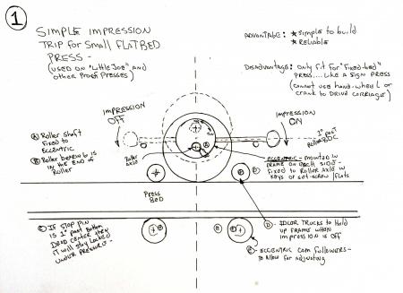
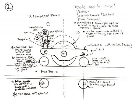
During my studies, I found two possible designs: 1- an eccentric operated, like on the “Little Joe” press, and 2- a toggle trip used on several larger presses. Below are rough sketches I drew up just to get my head around how they’d work. (please pardon the rough nature… they were drawn at the airport, while traveling.) These are the only two I discovered that actually looked workable in a small shop.
The Eccentric design (sketch 1)- is used on the “Little Joe” press as a throw-out, and other presses as a pressure adjustment. It is simple to build and reliable. The disadvantage is that it is limited to “Sign Press” machines, since the bearings are in the roller…. and thus you can’t use a crank to turn the roller, or move a movable bed.
The Toggle (sketch 2)- looks promising to me, but is more complex. It (or variations of it) are used on a number of larger proof presses. The advantage is that the roller bearings are in the carrier, and thus can crank the roller if you want to. This would allow it to be used with either a sign-press, Vandercook-style press, or a movable bed like a Poco Proof press.
Both designs have both advantages and disadvantages. I like the simplicity of the eccentric, but want to be able to crank the roller (or cylinder) like the the toggle design allows.
Does anyone have anyone have an alternative or hybrid idea? Or do you know of any better way of solving the “printing on the backstroke” problem? (maybe lower the bed?)
Thanks
Dave
aka winking Cat Press
trip1.jpg
trip2.jpg
What if you mounted the rails on top of Challenge quoins, or that type of multiple wedge mechanism that Challenge quoins have. Then you could mount a rotating shaft going across to both “quoins,”, and you could take the press on or off impression with a quarter or half turn of the shaft, which would move the wedges as necessary. If you didn’t want to use a rack and pinion arrangement to move the wedges, you could use a small crank and connecting rod. (I can’t remember what type of mechanism is actually in a challenge quoin to move the wedges).
System employed on a *Galley* proof press in my (authors) custodianship.!!
Considering the age and time frame quite sophisticated. i.e. the bearer rails are cranked up and down - micrometer thread adjustment to accommodate image/type matter straight onto the bed or with standard galley or bedplate.
The entire carriage traverses left to right and vice versa, on the left hand stroke it positions the feed board above the grippers and side lay, then (carriage) is transported to print from the hard rubber imp. roller,!
At the limit(s) of the traverse, in both cases the self inking rollers are lifted and the impression roller is dropped for impression.
The modus operandi is achieved via two double ended ramps (in either side frame stanchions) on the first pass the inking rollers are down and the impression roller is up, soon as the carriage reaches the grippers the inking rollers are triggered to lift and vice versa, very simple and very efficient, via the 2 steel ramps/wedges, triggered at both ends with limit stop actuaters, makes for a fairly quick feed rate with good register - if needed.
Hope this helps, and good luck, Mick.
Apologies and with hindsight, after re-reading Your original schematic, the above is very close.??
I should preface my comments with saying that I’m planning a fixed-cylinder, moving bed press. I’m not sure if my trip mechanism could be adapted for a fixed bed, moving cylinder press. That said…
What I’ve been planning for my press build is an over-center eccentric. Basically, a large outer bearing race containing a smaller bearing race off-center inside it that holds the impression cylinder shaft. As long as the “on-impression” position is swung past the lowest point on the eccentric, the upward pressure caused by the action of printing will tend to hold the cylinder on impression rather than kick it off.
A simple handle attached directly to the eccentric could serve as throw-off. This should be aided by a spring pulling the lever to the impression position. So to trip you pull the handle against the spring and to print you let the spring pull the handle back.
On my press I plan on using a compound lever fixed to the cheek of the press for better leverage and to shift the throw-off away from the crank. I’ve attached a couple of images of my design for reference.
OnOffOverlay.jpg
ImpressionOff.jpg
ImpressionOn.jpg
An addition to the above: The pictures are a little small, so I’ll say the depicted throwoff gives a cylinder lift of about .03”, so small but plenty to clear type height. This is also adjustable by changing the position of the shaft bearing and playing with the handle/lever geometry.
Also, here’s a shot of the eccentric without the lever or crank in the way so you can see what I’m doing here. The throwoff bearing is a very large pillowblock bearing with an insert in the bore. Off-center in the insert is the smaller bearing for the cylinder shaft.
I hope that’s all clear as mud!
—
Michael Hurley
Titivilus Press
Memphis, TN
Eccentric.png
Perhaps a little research into the system(s) employed on some of the Big letterpress cylinders, - Heidelberg, Tirfing, Johannisberg, etc., - whereby the Cylinder(s) just jack up a few thou. on the return pass, via powerful hydraulic,s.?
** Maybe just a tiny version with a pair of Wheel Cylinder expanders from Your auto/car/truck, **
All- thanks for the ideas, and input! As with any design process there are a number of possible solutions, each with it’s own advantages and disadvantages. Continuing the discussion, I’ve got a few questions and/or comments:
Geoffrey- I looked at the idea of a falling bed, rather than a lifting cylinder. Using a quion-style mechanism is a good idea. One question: in your idea, is the cylinder fixed to the frame, like an etching press? That would work. IF it’s a travelling carriage, how would one keep the cylinder from dropping with the bed?
Mick- I follow you right up to the Modus Operandi…. how do the ramp / wedges trigger the lifting and dropping operation? Are they simply lifted by rolling up a little ramp, or do the ramps trigger a linkage of some sort?
Michael- your design with an over-center eccentric bearing is similar to my sketch #1, but allows for the axle to be “live”… which means that you can then use a handwheel to drive the press. I like it. One question: How do you link the throw-out to both sides of the press? (a yoke attached to the upper handle, maybe?) In my idea #1, that motion is by the axle-shaft which is fixed to the eccentric on both sides…. so turning one side turns both.
Winking Cat,! Sorry my ramble was not too clear.
On the Proof Press the lift and fall is actuated by front & rear sliders, basically in the form of sliders (in steel) that are contained in the side stanchions with rebates/shoulders at each end = one end the ramp section lifts the impression cylinder and lowers the inking train, after the first pass the slider(s) reverse the operation, i.e. inkers UP & Impression cylinder DOWN just by the contact of the exposed ends of the sliders meeting the Leather Faced bump stops at either end of the traverse of the carriage.
Hope this clarifies, if NOT apologies again for confusing the issue. Mick.
As I recall it, the Hacker test press had a fixed cylinder and the moving bed was shifted up and down by way of eccentric bearings beneath the bed, by hand lever. There was a set toward either end, and a set directly under the cylinder. I think during the print part of bed movement, all three bearings were supporting, but maybe only two at the extremes.
I’m not any sort of engineer and I’m working on my third beer but have you thought about lowering the water instead of raising the bridge? Some sort of wedges that could be moved under the bed?
Hmmmm. I’ll have to think about it some more.
Dave, I honestly hadn’t gotten that far in the planning. It hadn’t even occured to me that the ends would need to be linked until you mentioned it! But, of course they would need to be or they could bind and jam the cylinder. The easiest solution would be to extend the eccentric’s arm out past the rim of the cylinder, have an identical arm on the opposite side, and a rigid bar connecting them. Hmm….
John, I know your comment was directed at Dave, but it is something I’ve thought about before as well. My feeling is that for a home-built machine, at least, moving the cylinder is an easier process to do accurately than moving the bed. With the cylinder you only have to keep track of it’s two ends. The bed would need to have at least four points of adjustment and more likely six. That’s a lot of places to get and keep in alignment.
—
Michael Hurley
Titivilus Press
Memphis, TN
I am not knowledgeable about the engineering aspects to comment on specific suggestions. Based on my experience, I would vote in concept in favor of the mechanism used in the Line-o-scribe press that has a pressure adjustment knob on the side of the cylinder. You can set the pressure to zero for the return so that it is off impression.
At our museum in San Jose we also have a Potter proof press, with a foot pedal to raise the cylinder to move it off impression on return. And we have a Hacker Test Press; it has a mechanism to automatically move the form away from impression on the return, similar to many Vandercooks. (I am not actually certain if the Potter and Hacker raise the cylinder, or lower the bed, but I can look into it further if it would help.)
Matt
Great comments across the board!
mick… I think I get it: tracks cut into the sides act like cams to lift / lower the impression and/or inking. That’s not a bad system. Thanks for taking the time to explain it so my limited brain can understand it.
Geoffrey- I can see those gears turning…
Parallel Imp and John… Lowering the bed is a concept I’d not considered. I’ll have to study that further.
Michael- after my post yesterday, I pondered the problem with moving both sides… and it’s simple: just like you mention, a rigid bar joining the levers on each side. The Showcard “Special” has such a bar
Liber- The Potter press I’ve used in the past has the Toggle Mechanism,( as in my sketch 2) also operated by a foot pedal. I’ve never looked at a Hacker. A quck sketch of the linkage would be helpful.
All… continued thanks for your input!
W.C.P. Thank You for the *Nod* appreciated.!
Just to recap, yes the sliders are actually in the form of 2 steel sliders front and rear, carried in the appropriate close fit slots in the side stanchions, just triggered by the contact on the bump stop buffers, usually lubricated with a tiny amount of Graphite powder, *liberated* from the Linotype/Intertype dep., (now and then?) so we believe, normally used to lubricate and clean the Spacebands.
The sliders are in appearance, almost like looking at lengths of *Supercaster* or *Elrod* strip material, approx. 38 ems long and Pica/12 Pt. in width, precision ground and only lubricated with Graphite.
One more little pointer that may assist Your learning curve, Key into Google w/w/w etc. :- FARLEY Printers Proof Press, maybe inc. Schematics, usually the first entry that comes up, includes 4/5, shots of the Farley, the 3rd. 4th. shot gives a very good colour picture of the entire operators side view, showing the lockable calibrated mechanism for the height of the impression cylinder, including the handwheel for running up the ink, and more.
The operating mechanism is via the pictured top cross rod, with centrally located hand grip to ensure even thrust for the transport of the carriage, quite important to ensure even parallel transport, if when the side stanchions are not in precise contact with the rails, or mal-adjusted.
Same concept probably holds good, for similar style, hand operated machines.
OK I changed my mind about how to do this. This is referring to Michael Hurley’s diagram above, called Eccentric.png
Start with the larger diameter shaft that Michael shows. Chuck that shaft in a lathe and drill a center hole in each end, in the same position, but maybe 1/4 inch OFF CENTER. Then chuck the shaft in the lathe between the off center “centers.” Turn each end down to the smaller shaft size, so that you have two shaft ends on the big shaft which are on an eccentric to the middle part of the shaft. Mount the impression cylinder on the larger diameter middle of the shaft, with bearings. Then mount the smaller eccentric shaft ends on pillow blocks.
Then all you have to do is come up with a way to rotate the larger shaft, say a quarter turn, and hold it in that position. Since the shaft ends are on eccentrics, the shaft will raise and lower the cylinder. You don’t have to worry about mechanisms for raising and lowering each side because the eccentric shaft is one piece and that will happen automatically.
In the pioneer village where I volunteer, we have a platen press with this type of mechanism on the platen for the throwoff. That’s what made me think of it.
To assist W.C.P.s, possible learning curve and an addendum to Geoffrey,s entry above! :- engineering simplification, i.e. take the proposed steel stock, locked up in a conventional *Independent* 4 JAW chuck (NOT self centreing) on conventional centre lathe, (Author uses Colchester Bantam Lathe as weapon of choice U.K.)
Position the stock off centre by as little as 10% (will give all the eccentricity for this proposed op.) centre pop the end for subsequent mounting between centres, conventional centre pop drill in the tail stock.!
Without removing the stock from the 4 jaw chuck simply turn/machine the first eccentric, exactly sufficient for the proposed length of bearing area, BUT leaving an excess of at least 1/2” protruding,?
Reverse the stock end to end in the 4 Jaw chuck, of course, making sure it is gripped in exactly the same plane longitudinally, turn/machine the second eccentric.
Eccentrics sorted.!!
Rise and fall. On and from the short extension after the first pass, machine or even file by hand 4 flats, to create a Male (square) receiver, for something as simple as the Bottle Key spanner from/for Oxy Acetylene set, ready made handle/lever slid on to the 4 flats, (not critical) but ideally to swing from 12 o`clock to 3 o`clock.
Any concern about the eccentrics bucking up and out of contact on the impression pass, simple as incorporating a tiny pear shaped gag block to act as retainer/stop, like a traditional vintage keyhole cover.
If the bearing surfaces of the eccentric shaft are to be close fit in the side stanchions, oil holes should be incorporated primarily, better yet for an efficient overall job, perhaps *go the extra mile* and incorporate *OILITE* bearing material, self lubricating very hard wearing.
OILITE, is excellent material to machine and *turn* from, bettered only by Lignum Vitae, as used in U.S. Nuclear submarines as prop shaft bearings apparently.
(Author) I rest my case and the Mouse is recovering from R.S.I.
By now, the Mouse and I must have provoked just a little Trawling for more info. May even have planted a few seeds, for the new ones.
Good Luck. Mick
The Eccentric design
Reprex defiantly and I also believe Asbern used an eccentric shaft and bearings in the cylinder on their hand cranked cylinder press. Asbern did it the simple way and geared the crank to the cylinder gear. Reprex used a pin and slot drive to connect the cylinder and eccentric shaft, and the eccentric actually rides in the bore of the crank handle. The way Asbern did it is the simplest from a home machining stand point the only real complicated part is the eccentric shaft and that is really a pretty simple task to turn on a lathe.
Mick, thanks for your comments! All very good points!
Regards, Geoff
For what it is worth, I think the the Potter style trip mechanism works quite well. I have owned one for about 5 years and find it a very simple and low maintenance method of achieving a trip function.
One point of interest, the cylinder is on an eccentric type pivot, but it is also held down by a spring (trampoline style) on the underside. I have never fully tested it, but wonder if it is actually able to print a solid for the whole 17 inch width of the bed.
Steve
All- Excellent ideas, comments, and discussion! Obviously, there are a number of smart folks here on Briar Press.
The eccentric shaft concept is similar to my original sketch #1 in functionality, but has fewer parts. If you combine that idea with Michael’s “slightly over center” locking idea, you wind up with a simple, relatively easy to machine, and probably quite reliable system. I like it.
Yesterday after work, I machined a 3/8 throw / 3/8 shaft out of gnarly old scrap stock ( an old iron sash weight!), and set it in a mock-up frame.
Doing so, I see a few things:
1- the throw is obviously 2x of the eccentric’s offset. Thus with a 1/4” offset, you get a 1/2” total lift. I’m thinking a 1/4” to 3/8” total lift is about right….. so a 1/8 to 3/16 offset would be required. I used a 3/16 offset to get 3/8 lift
2- the greater the lift, the larger the diameter of the original stock must be, and thus the larger the bearing inside the roller must be. To get 3/8” lift, with a 3/8” axle in the frame you must use a 3/4” diameter piece of stock, and 3/4” ID bearing inside the roller. That my be problematic for a small roller diameter.
3- machining such a shaft is easy, but hard on your bits. I did the same thing while making the eccentric trucks. However, it does require a lathe with a bed longer than the shaft. With a 12” long lathe, you can only make a 12” long shaft…. with ~9” print width.
So…. here are my conclusions so far:
1- the eccentric shaft would work perfectly for a cylinder style machine.
2- for a smaller roller-type machine it may be problematic due to the required bearing size inside the roller. For that use, mounting the eccentrics in the frame (as in sketch #1 at the top) might be the better solution.
3- The eccentric shaft requires a lathe large enough to handle the entire length of the roller shaft, while the “eccentric-in-the-frame” design can be made in a very small lathe. This may or may not be an issue.
of course this all brings up yet another question: How much lift is actually required? I guessed 1/4” to 3/8”, but after making the test-shaft it looks like too much.
Again… thanks for the ideas and input.
The amount of lift the cylinder needs to clear the type is really very little. I measured the lift on my Reprex at 0.070”. If your cylinder is geared to the bed then, the lift is limited by the pitch of the gears.
Dave, I’ve been thinking more about this throwoff idea and Geoffrey’s eccentric shaft should work fine for something like a Showcard-style press where you grab the cylinder carriage itself to move the cylinder over the form. There’s no easy way to crank the cylinder, though, since the cylinder sits inside the carriage stanchions while the crank will need to be outside of them. You’d basically need to pass the crank shaft through the stanchion, have a drive pinion on the other side of it, and a bull gear on the face of the cylinder that the pinion drives. This was why I made the throwoff eccentrics the larger diameter and the cylinder shaft the smaller one passing through the eccentric. I can just join the crank to the cylinder shaft and be golden. Gears are expensive compared to bearings.
Also, honestly, ball bearings are likely overkill for a hand-cranked, low-speed press like the ones we’re contemplating here. They’re just easy to come by, low maintenance, and everyone thinks of them first. A traditional, oiled plain bearing would likely be fine as well as being very rigid and high-precision if made correctly. They’d be especially good for the throwoff bearings since those don’t need a whole lot of movement.
McMaster-Carr carries basic Oilite plain bearings up to 3.5” inner diameter. I’m thinking of trying them with my design as they’d be much cheaper than the large pillow-block bearings I’ve currently got spec’ed.
—
Michael Hurley
Titivilus Press
Memphis, TN
all…. I have not forgotten about this thread. I was travelling for the last few days. BUT, I’ve now got a new shaft chucked up in the press. This one is going to have 1/8 inch throw on a 1/2” shaft. That’ll fit the small press quite nicely. I’ll post pics in a day or so.
Michael- with a cross yoke to tie your eccentrics together, there is no reason your idea will not work perfectly. I look forward to seeing your design and eventually your press.