windmill ill?
greetings.
before I expose my issue, I’d like to thank you all for existing.
I’ve been learning to run a ‘54 windmill for 3 years now, and it has been a hell of a journey. not that hell—thanks to this community.
the problem I’ve stumbled—the lower right corner of the form holder backing seems dimpled, forcing me to make funky packings to get a decent, dignified to paper, even print, all over the form.
is this a sign of print strenght abuse in that corner?—since it’s the guide corner. or it is normal? how to overcome this?
I’ve been strugling to understand this in the last 3 years, and I’ve spoke with a 40 year experienced windmill printer—he told me that it’s almost impossible for the “form backing” to dimple.
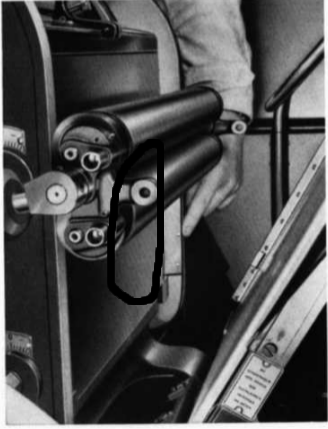
but crap, I feel it even with my hands that there’s some kind of a dimple there (see attachment please, and ignore the rollers’ existence).
is there anyway I can solve this? I’m tired of funky packing/makeready…
apmubsstobriarpress.png
Are you saying that the main platen face is damaged, if you are then it would be very expensive to repair to bring it back to tolerance and you may be just as well putting up with excessive make ready
I think he’s saying there’s a noticeable dimple/dip in the lower side of the bed opposite the flywheel, not the platen.
If the bed is noticeably lower in one corner, your type material must be lower there too, which must cause your rollers to miss that area and it to not get inked. Either this, or your rollers are set too low so that they do ink this low area, which would make any type matter on the other edge of your form over-inked. This seems like an annoying problem, and if there’s damage to your bed there’s really nothing you can do about it.
Where are you located? Maybe someone else can come help you out with this.
Are you printing from type normally? If you’re printing from photopolymer the base will not notice the dent you think is in the bed and the problem lies elsewhere.
thanks for your quick feedback!
i’m printing with type only—200+ drawers of very old and used type.
well I guess that’s it—I can’t do much about it, unless it is possible to replace the bed… is it? :s
is it wise to back up the bed with pasted tissue on the dimpled area instead of packing/makeready?
Tissue will quickly compress and give you more trouble than it’s worth I think. If you find everything is inking ok, I would prepare a tissue makeready template that you can use on each job on the platen, not the bed. The amout of extra packing required to compensate for the damage to the bed will be the same for every job, so it will become an extra step in your set-up.
Replacing the bed is an option, but it would be cheaper to buy a new windmill.
I really can’t see how this would ever happen, so make sure the problem isn’t something else.
Fifty years of steel punches cutting asbestos and copper gaskets ?
Fifty years of steel bodied numbering boxes ?
Fifty yers of the scrubbing action caused by the not locked inch over hang of perf rule ?
More likely fifty years of hard work and half of that being pushed to the limit , not every machine out there is like it was built , unfortunately having the bed ground is a lot of money if you find an engineers up to it , then you have to cope with the filler bedplate you would end up with and a weakened machine bed , sorry the make ready in that patch it is then .
yeah, that’s the solution I came up with… I had a hope though that I was wrong…
also the guide bar is doomed. I can’t even take it off because the pump side screw is doomed too. I get better register without guides than with guides… what can I do to remove that guide holding bar?—guess its cheaper than the bed…
thank you once again!
Do you mean the lay bar on which you fit the brass gauges?
For the dented Bed, Devcon makes a 2 part Epoxy which is metal based, it is used to fill cracks and casting flaws in cast metals, Once cured, it can be sanded, drilled and taped.
http://www.brownells.com/.aspx/pid=5808/Product/EPOXY-METALS
@typenut thanks a lot for the link! that’s what I was looking for without even knowing! :)
@peter luckhurst yes, exactly.
The screw you are referring to is the one on the right to square the lay ?
I have explained on earlier posts how to remove the assembly for replacement of parts it takes twenty minutes in and out . whittenberg have all the components you will need to replace if not then i can source for uk ,i keep second hand parts for this or can source neww where needed , the assembly comes out in one lump with a screwdrive and a ring spanner two grub screws and a ten mm spanner if i remember right .
peter, I can’t unscrew this part as the screw is damaged… tomorrow i’ll take a picture if I remember. I must break the hell out of it, don’t I?
rgds & thanks
Not necessarily !!! Beating the bits that hold the lay is a bit harsh and the bits break really easily too !
what about sawing?
Not necessary .
You havent put up the location of said bad screw there are reasons i ask !
There is a post about this part and a picture was added to show the parts i dont know how to find it but its
in here somewhere .
If you get a pic of offendind part i will tell you how to get it out ,
sorry for the delayed pictures, but here they are:
(pump side)
bottom
top
That looks like the adjustment screw that enables the guides to move about up and down. Half of the screw is missing as well as the locking nut that would be on it. That screw can only turn out so far so you’ll probably have to remove that entire rod with the holders. Someone else will probably verify what I’m saying. Ron
Here goes then apmub.
Look at the block the screw goes through , you can only see that oblong bit,
It really is not oblong as it has a shaft on it , looking at your bottom pic, the block you are showing is fitted to the platen with a bolt and a grub screw , the block you have shown is actually shaped like a square headed hammer , a bit like thors hammer , the handle of that would be orientated down ward if you close the platen 75 % and remove the delivery stanchions ,pull the delivery backstop as close to the front of the press as you can you will then be able to get to the parts to remove the lay bar there are one bolt and hidden in all the crap a grub screw that you need to unscrew with a flat driver , it is very short so dont drop it when you undo it
a ten mm spanner will undo the bolt , dont put a screwdriver into the split casting to open the split or the casting will break , the bolt for this is located on the back side lower portion of platen if you feel the front bits you have picturd and bring you fingers to the lower bit and look you will see the pinch bolt you need to unscrew and going into the side of this bit that is pinched there is a grub screw in among the crud you must undo it carefully not drop!
On the left side of the lower rear of the platen you will find exactly the same to mrelease the left hand side , sorry this is confusing but i cant find the thread on briar that i previously did this for someone else ,it has the best description you could get and some kindly soul has put photos on it too , i cant find my parts book to make this easier .
once you have released the bolts and screws you can wind the platen open agin (by hand) lean in and push the whole lot toward the back of the platen and the lay bar will come out complete , the broken screw bit can then be removed its available as a replacement part as can the bar itself , the screw has a collar on the bottom held on with the tiniest taper pin you will ever have seen ,take care to work out the right way to tap it out . you can straighten the bar yourself no problem ,dont try to do it assembled in case you damage the mount blocks they are cast and break easily . You can message me if you cant find the part to undo ,i will try to find the thread again and my parts book , i think you will find it ok with the above , be patient and careful its easy when you know how and if you take care to not drop anything the grub screws are difficult to fish out if you drop them!!!
Found it , Check out Almondine2 Heading as “bent windmill lay bar “
Your top photo ,upper image ,actually shows one of the bolts you need to release !If you could see a bit lower in the image ,beneath the muck is the grub screw you want to undo ! Both sides are the same once you have done one the other is easy.
i think i got it! at least the theory… thanks!—i will get to the press later in the afternoon. i’ll post a new thread regarding the grippers. they are hurting the paper, leaving a straight line on the stock…
You are printing on thick old stuff that is highly compressable and it has no memory , your best option really is to have a bit of waste to trim away . The grippers are sprung so you sort of have to live with it , you may however be able to put a small piece of the compressable rubber foam as used for stand off on cutting forms inthe gripper arm away from your stock area ,this would help take some of the pressure off the stock but it will take a while to get thr thickness right in order that it relieves the pressure enough to stop the marks without the sheet slipping out of the gripper as it swings across the platen .
It is possible that your packing is part of the problem too , especially if the packing and the stock together exceed the thickness guide on your delivery stanchion .
the given thickness is what the design allows for and exceeding this only invites grief of one sort or another !
for packing, i’m not counting neither stock or makeready thickness—just fit the packing to the gauge (1mm it’s what the portuguese plate says) then i add the makeready sheet, and run the stock…
you’re saying that packing + makeready + stock must fit in the delivery gauge? then i am overpacking…
The gauge is the total that you can run includesyour job sheet . if you are running 1mm board then you are running with no packing to be at the correct thickness ,obviously you will have to carry a tympan but you will have to use a sheet of tissue / onion skin for that so you can get your patching up somewhere on the platen without the grippers tearing it off , thats about all you can do .
so, getting back to the guide lay bar removal issue—i was able to remove the pump side screw with a normal screwdriver, but the wheel side screw has to be with a hexagon shaped screwdriver? it is extremely dificult to reach. I couldn’t get it off…
also, i’m affraid that the wheel side has no bolt like the pump side?..
Look again at the first photo above that bolt you can see is the one that releases the fixing along with the grub screw that is right next to it you have to dig in the crud to find it , there is another on the drive side too they are just difficult to find is all.the bolt you can see in your pic just look 40 degrees below to the left ,its within 1/2 ” of the bolt . Look at the pic Almondine put on the post i did this a while ago .
At the top right of this page here there is a search box ,type “bent lay bar ” in and its a few entries down the list , that thread has photos of it . The left side the grub screw goes into the block from the left , You need to operate the lay manually raise it right up and scrape the crud off and its about 1” back.
You need to close the platen to get at the pinch bolt it is beneath the platen and looking from the front it is on the right side of the block ,if you are a bit tubby you may have to take the feed board off to get in there , i have the advantage of being skinny .
Pump side screw ,it is a grubscrew you have to Hold the lay in the up position and get the screwdriver in from the left it does get in there but take care you get decent purchase if you cant then remove the spring that is in the way ,i just let the screwdriver shaft hold it out of the way but i have the advantage of knowing how to get at it , Its just fiddly .
Believe me i accept it seems impossible but it really isnt once you have done it .
hello peter, first of all thank you for your guide chat—you are helping me a lot!
i’ve seen the photos on the “bent lay bar” thread but i’m affraid my model is different.
as you can see on the photo below, I coulldn’t find any bolt. and the grub screw is hexed—is this the grub screw?
the pump side is ok, removed the grub screw already with no big deal, i’m dubtfull in this side though…
is it possible, that my model if different?
wheel side
There are small variants , ie like the grub screw being a hex key not scrwedriver , however this side of the press is assembled in the same way as the other side you just have to get to the bolt , the grub screw goes in as you can see , now close the platen and feel under the block the bolt goes into the other side of the block its a ten mm bolt and it closes a pinch fitting exactly the same as the pump side , it is there i assure you . when you have loosened both sides of the blocks the unit will just slide out in the direction left as you see it in this pic. the grub screw is only there to ensure that the block is seated correctly in the hole there is always a pinch bolt that hold it tight in place . It could be the end of the pinch bolt that is visible in this pic it might be a good idea to check ! I have found half a dozen variations over the years so it wont surprise me if it is , i will be a bit red faced if it is as i have never found one with the bolt accessed from the front !
Apmub i have also just noticed the adjuster screw on the flywheel side is not the right one so it looks like you are replacing both of those when you reassemble it , you should replace it with the correct part or you may find it makes resale difficult later on ,
yes peter, i was going to tell you that, cause today i was chewing my mind on this… it is obviously an unoriginal part…