Pilot Press Side Arm Help
Hello -
I hoping someone can provide some insight to a problem I’m having. My left roller is not in sync with the right roller and I believe it has to do with the side arms. I have found that there is a lot of play in the left side arm where there is virtually none on the right.
I have easily removed the spring/taper (?) pin from the left side arm, but cannot remove the pin from the right side. The weird thing is that the right spring/taper pin moves in and out ever so slightly when I lift the left side arm up or down. So it seems that the right side spring/taper pin isn’t doing its job properly and allowing the rod that connects the two side arms to rotate slightly. What do you guys think? Any suggestions for removing the spring/taper pin on the right side?
Here are two pictures and two videos. Thank you!!
Right Side Arm:
https://vimeo.com/96753060
Left Side Arm:
https://vimeo.com/96753365
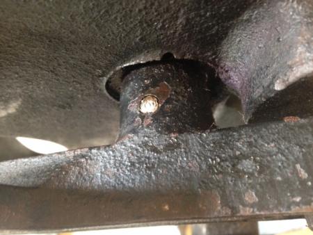
RightSideArm2.JPG
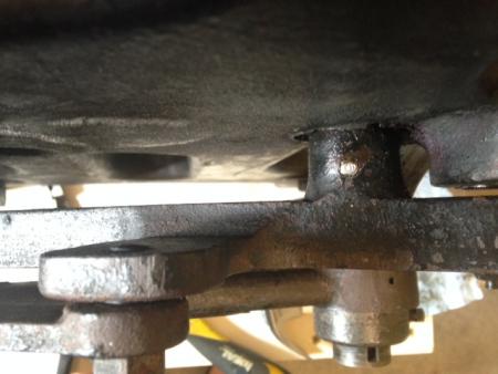
RightSideArm.JPG
Margaret -
I concur with your diagnosis. Yes, the side arms are not moving in unison, and that’s the problem.
You may get away with simply replacing the tapered pins with new ones.
The only way I know of to remove the tight pin would be with a drift pin and hammer. Heat might help, but you may be able to do it with just a drift pin and a somewhat heavy hammer.
That pin is likely hardened steel and may not be very easy to drill out.
If simply replacing the pins does not work, the more complex and expensive solution (if it’s really necessary) would be to take the entire press to a machine shop that can mill oversized holes for larger pins Although milling oversized holes would weaken the link at that point, it’s not a heavy stress point - as, for example the side arm links to the rockers (which are a common failure point). All these pins need to do is keep the roller arms aligned as the rollers roll, and if they are well lubricated, the load on these pins is relatively light.
Now, the other - perhaps more important question is “how does this really affect your inking?”. All the rollers do is roll over the form. Inking with a brayer is not done at a perfect 90 degrees, if the rollers roll at an angle (as long as they roll and do not slip), inking really should not be affected.
Before you invest in some pretty expensive machine shop work, I’d do some printing and see if this simply is a “quirk” of your old well-worn press which really does not affect the quality of the work you can do with it.
- Alan
(Old printer who’s repaired and restored a number of presses over the years)
There seems to have been a change at some point in the pin positioning in these presses. If you have a newer replacement arm it may not align properly with the older pin holes, or vice-versa. A loose arm can be a real problem, causing the rollers to bind and possibly break. You will need to remove the pins to see how the arms align, and if all is well you’ll need to replace the pin that is loose - a common item in most hardware stores. If it doesn’t align properly you will probably have to take it to a machinist for a permanent remedy.
Paul
Hello
In many applications a roll pin is interchangeable with a taper pin. However if the hole previously had a Taper Pin you MUST drill the taper out of the hole to the proper
size for the New Roll Pin. Roll pins have the advantage of using a straight wall hole you can make with a twist drill.
Taper pins require a taper hole that MUST be prepared with a taper pin reamer.
Taper pins are soft steel (can drill them out) ….roll pins are hardened steel (difficult to impossible to drill out).
Not see taper pins for sale in hardware stores only place I know to get them is McMaster Carr…. Roll pins available in well stocked hardware store.
Good luck on your repair project
Best,
James McGraw
I appreciate your responses!
It does seem that rollers get hung up a bit since they are skewed. So it seems best to try to remove the pin. I don’t understand what the pin actually does. If I shine a light on the left pin hole it appears that the pin doesn’t make any connections, just seems like a hole straight through the arm.
Is the pin on the right side different?
Can anyone explain the mechanism?
Has anyone drilled a pin out with a titanium or cobalt drill bit? Any advice?
Many thanks!
If you can see right through it, the pin is missing from the left side-arm. Removing a taper pin is usually not a problem. On a C&P Pilot the small end of the pin will be on the bottom, and will need to be tapped with a hammer and a tool called a ‘pin-punch’. It might be easier to find a source locally for taper-pins, and buy an assortment that look to be about the right size, find the one that fits, and return the others. The pin will need to be inserted from the top, putting in the smallest end first. There should be no need for drilling at all.
Paul
Hi Paul -
I have already removed the pin from the left side and that is why I can see right through the hole. It was very easy to remove; however, I cannot get the right side to budge yet it moves ever so slightly when I manipulate the left arm. I have tried hammering it out and it still does not move.
Is the right arm different somehow?
BTW, the left pin doesn’t look like a taper pin to me. If it is a taper pin the differences are minute, but the pin does have three lines that run down the length of it. Any ideas? I’ll take a photo and post it.
If your second taper pin is slack but will not willingly come out. probably/because, it is quite usual for the wear to make small shoulders on the pin, with a second pair of hands gently ease the arm backwards and forwards, a few Thou. imitating the wear/thrust, as you imply loose already, the problem should become clear, and has been observed already they (taper pins) are factory fitted the quickest easist way, i.e. from the top down, making extraction from the bottom up.!!!
Generally when fitted properly/originally they were taper reamer fitted, with pins that made a good fit, but were usually longer by about 30% so that both ends protruded, when tight, by an observable amount.
When they appear flush at both ends, they have probably been vandalised prior..??? If the D.I.Y. option is attempted the first step would possibly be to ascertain IF imperial rake/angle taper pins are available,!!
3 lines probably implies metric rake, taper pin, bodged into imperial original hole? Here U.K. would and have solved similar problems thus:- Acquire imperial type taper pins, selection of, one hand taper reamer, ream the first side to accept smallest taper pin, then BEFORE attempting the second side, to enable synchronisation side to side, secure/torniquet the first repaired arm in solid position, then 2 lengths of Studding (threaded rod) bolt the roller hooks together where the stocks would sit, hand and brain and eye, perhaps, even with steel rule, align the arms accurately, secure with torniquet, the (unrepaired) holes will almost certainly appear out of line, even by as little as .003 to .005 thou, but of course amplified considerably at the extent/length of the arms, IF/WHEN once secured in the correct synchronisation, taper ream the second repair refit, make sure that any new taper pins protrude a small % this is achieved with a selection of pins, with small copper hammer and care until good fit is achieved, with the lightest of taps, initially, this can be achieved, for test prior to eventual final tapping in, a copper hammer @ as little as a few ounces is more than sufficient to tap taper pins in.???
Roll pins were not invented, when our first such repairs were being performed, and we would not have used them anyway, they are Hard Steel, and would crucify the parent material, taper pins are meant to be sacrificial for this very reason. Good Luck.
The description of three lines running down the sides sounds like a roll pin to me. It may have been used to replace a tapered pin and that is why the arm is loose — the roll pin would not lock the arm in place as would the tapered pin.
I’d suggest a possible way to see what is going on with the right side pin. Find a nail that looks to be about the same as or slightly smaller diameter than the pin in question and file the pointed end of the nail flat across the nail, and with a small hammer carefully place the flattened end on the lower side of the pin (which should be the small end) and tap lightly. If it is a tapered pin it should move. If it is not a tapered pin you still may be able to drive it out with the improvised nail/pin punch.
If you have a small ruler graduated in millimeters or 32nds of an inch, measure the holes on the two sides of the left arm, top and bottom. If the pin was a tapered pin there should be a noticeable difference, but you’ll have to look carefully as the difference is slight.
Bob
Hello -
I am going to get a drift punch today and see if I can get the right pin to budge.
Here is a picture of the the pin from the left side. The pin has a total of three lines running down the length and in the photo you can see one of the three. I used my micrometer to measure the ends and they are pretty close. One end is .222 and the other is .2175. One side is a little more beat up so it might be mushroomed?
So this press should definitely have taper pins in place on the arms?
photo.JPG
If the person who installed that pin (which is not a tapered pin) knew their business they probably drilled out the holes in the arm and shaft to be straight. But I’d still suggest measuring them to be sure. If they were drilled out you’ll have to get them reamed tapered again for the best repair. A lot depends on what is on the other side — which also could have been treated the same, drilled out.
The advantage of tapered pins is that if they work loose you can tap them back in and tighten things up again. With a straight pin, once it’s loose you have to fit a larger pin to tighten things up again.
One possibility with the right side is that it is a tapered pin and it’s tight in the shaft, but the holes in the arm have been “wallowed out” by the wear induced by the other side being loose.
Bob
Bob -
That makes a lot of sense, thank you for your response.
You may find that even with a suitable pin punch, upside down with possibly little or no clearance for even a small hammer to swing UPWRDS is always difficult!! if not impossible. Her U.K. when all else fails we Would, and Have, placed a washer on the top, just big enough for the taper pin to enter, with a ball bearing on the bottom, immediately under the flush tail of the taper pin, and then with large self grip wrench, or plumbers water pump pliers, pushed the pin, up & in. even .003/.004 thou will give access and positioning for a pin punch, with copper hammer, when the ball bearing has *cracked it/freed it* initially, the gentlest of taps will push it out, + with even a minute protrusion above, tapped from below and gripped/pulled from above shoul be a cynch.
Assuming Self grip wrench,s and plumbers Water pump pliers are compatible to U.K. style,, large ones with infinitely adjustable jaws will (A) span far larger items than the problem in question & (B) have phenomenal crushing power or in this case, have equally phenomenal pushing power. ???
We have occasionaly had to resort to this method, I.E.ball bearing, substantial washer and LARGE water pump pliers, on a taper pin situate, on a Thompson British Auto Platen with virtually no clearance under, THE taper pin was as big as a biro pen, This tip came from a Bona Fide printers engineer, his firm would have hired us the proper service tool, at a price!! but a nice Bottle of brand (X) was cheap, bribery and corruption was alive and well way back, it is not a New phenomenon, so we believe. Good Luck. Mick.
I reiterate, some attempt should be made to obtain correct alignment, before fitting the second taper pin?? just fitting willy nilly, will surely just replicate the original problem.!
It would be so much easier to measure the pins in question and purchase 2 or 3 around that size to save from making too many trips to the hardware store
. Leaving the existing pin in place would certainly be easier. Since the pins can only go in one way there should be no question on alignment. This seems like an awful lot of discussion for a simple problem with a 5 minute fix.
Margaret,
If you prefer a talk-through, live… give me a call.
651.334.8159.
I would be happy to help. I have addressed this very situation many many times.
Tom
www.tandtpressrestoration.com