Studio-Platen 6x9 “full chase” test
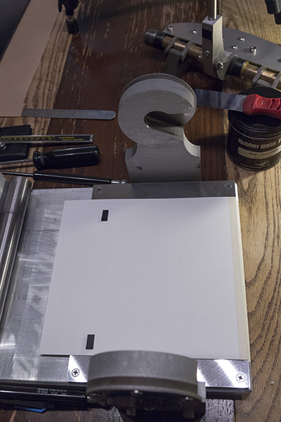
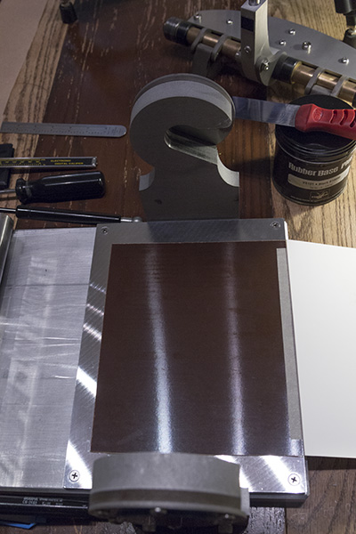
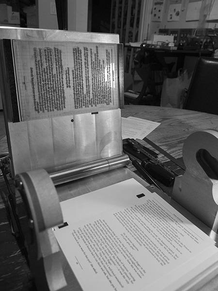
This test went very well and demonstrates the surprising power and accuracy of the little S.P. 6x9. The paper used was 60# book uncoated offset. I have been using .010” polypropylene “Yupo” in place of traditional tympan. Behind that is a sheet of .030 phenolic and behind that is the Mic-6 platen work plate. No makeready was required for this test; I got even coverage and a really healthy bite right off.
Please enjoy a short HD video of the test here: www.youtube.com/watch?v=5j5Xv_g2vdU
SP6905.jpg
SP6906.jpg
SP6907.jpg
Congratulations- this is a very interesting press. Would you mind talking a little bit about how much you spent on materials and how much time you have invested in producing it? Is there anything you’d do differently were you to start from scratch?
Daniel Morris
The Arm Letterpress
Brooklyn, NY
Got any detail shots of the corners of your plate, or close ups of the printing? I’d be interested to see how that fulcrum works- looks like you’re using the leverage of that device in the right hand side of the photos, inserted into those two half-S/Hook shaped parts, to toggle the impression together. Are you unable to leave that engaged/do you have to remove it every time due to the swing-open nature of the press? Is the plate inked upright like that?
Very neat!
Can it be fitted with a conventional chase, or are you limited to a ppt base?
Daniel, Thanks! I have been working on this press for about 2 years and this is it’s 4th and final iteration. I don’t know what I must have spent on materials and services ….probably around 2K but this figure also includes a lot of wasted materials and services. If I started again from scratch I might add a motor and a flywheel! But seriously I really love it just the way it is …and it’s perfect for us; it lives in the corner of our kitchen and when it’s time to print we get it out, when we’re done, we put it away. Performance wise it has exceeded my expectations and I’m extremely pleased.
Haven Press, There are some detailed pictures as well as a video link on my first post here: http://www.briarpress.org/40965 The impression lever must be removed and re-inserted for every impression …I just couldn’t figure a simple way around that.
Oprion, I designed the press around .918 standard. Personally, I don’t have any type, quoins, furniture, etc. but a chase system could be made and attached if needed in the future. Thanks.
Billy….. one of the most important aspects of a press is the quality of the image it puts down. For a home studio, hobby press, or any other non-commercial application, quality is everything. (Speed is not really a factor). Looking at your test, it appears that your press is capable of very nice work indeed!
When I first looked at your design, I wondered how well it would print since there is no platen adjustment…… but it looks like you’ve overcome that by being very precise during fabrication. As the press gets worn through use/damage/oxidation you may eventually have to use more makeready, but that’s one of the trade-offs you have to deal with in order to keep your design simple.
W.C.P., Thanks! The press can accept paper from .001 all the way up to .110 while maintaining perfect parallel. To do this, material can be added/removed, in any needed combination, from beneath the platen work plate as well as the 2 steel impression blocks. I use mostly .015 & .030 glass/epoxy board for this to maintain rigidity. Additionally, any thickness of plate material can be used with 1 boxcar base. I have been using Toyobo KF152, KM73GR and .062 copper plates, all with terrific results.
Hey Billy- I took a look at your other post.
As I’m sure you’ve noticed, a lot of tabletop press are designed to be bench-mounted. They rely upon a larger piece of furniture- bolts assist with keeping them stationary, and they’re more portable as a result of not requiring a bottom frame. They must make the impression method more compact as a result of designing within a more compressed space, so you see a lot of large handles etc.
Presses with feeders where an operator must insert a chase often need the feeder to move out of the way as a method of allowing the operator to both reach into the press to remove the chase/position plates etc., and to do some spot underlay or change the packing.
An eloquent solution used on some of these presses is to swing the feeder out of the way.
I mention both of these options, because what if:
A. you added four basic bolt positions- to allow your press to mount to a table or bench, even temporarily.
B. You were to then build an extension with some sort of assembly that would allow the handle to rotate/turn out of the way when flipped to the entirely-unengaged position? And allowed for some ‘play’ to then swing it back into position for impression?
This would surely create a situation where less fumbling was necessary, and I am certain with your design and fabrication abilities you could probably pull something like that off?
(You can see why I mention both the feeder and the mounting before mentioning my suggestion- because I am borrowing from problems solved by other machines in your design’s same tradition)
H.P., I have considered making simple L brackets for mounting to a work surface but the only place I have used this press is on our kitchen table. Quite a simple mod though. I also made a 24” handle so that my wife can use it too. Your suggestion for making a swing-away handle is a good one and I have considered similar arrangements, but I chose, at least for now, maximum simplicity over continued engineering, fabrication and testing. Besides, I’m a pretty big guy and don’t mind lifting the handle in & out. The longest run I ever do is 250 impressions and although it’s a lot of work, I’ve never seen a fully manual press that isn’t. To me it’s very enjoyable. Thanks!
As long as it’s enjoyable that is what counts. Consider them suggestions, I think your press looks like a good one.
Did you do all the machining yourself? What kind of mill do you have, if so?
H.P., Most of the shaped parts were designed in Adobe Illustrator and cut using waterjet: http://www.tritonwaterjet.com/ . Any precision bores and diameters were machined using only a small 7x10 lathe, again, in the kitchen. I did all of the drilling and tapping here too.
So you didn’t even use true 3-d CAD rendering- pretty impressive.
If you ever need parts milled/machined, my neighbors have a FADAL Machining center- message me for their info.
H.P., I don’t even have any 3-D CAD software, but for waterjet cutting, only 2-D outlines are needed. I think I would like to make friends with your neighbor!
Billy….. I’ve got a 7x10 lathe myself, and a drill press….. and that’s the extent of my precision tools. For my own presses I try to stay away from the more advanced tools like CMC and plasma cutters in order to make my designs more easily constructed by folks who might not have access to more sophisticated tools…. but that’s just my personal philosophy, not a criticism of using such devices.
I can see the benefits of the Hydro / CMC / Plasma or other means of cutting the complex shapes. There’s always a trade-off between ease of construction, available means, and intended use of the press.
By the way: have you done any calcs on it’s theoretical impression pressure? Since it’s a toggle mechanism, I’d guess it’s pretty high for a small platen press.
Also, I like the way you spread the loads out across the platen. I’m sure that is one reason it puts down such a good impression.
I agree with winking cat..re a swing out mechanism to pressure mechanism…look up presse a bras french direct litho presses eg voirin….made of wood but stong pressures…also congrats on engineering
WCP, I haven’t done any actual testing to find what the maximum psi impression would be, but it’s a lot. Theoretically, since it’s a short throw crank system, mechanical advantage is infinite but in real world terms, a 10” throw of an 18” lever moves the platen about 3/32”. I have exerted force in the neighborhood of 70-80 lbs and seen evidence of surprisingly massive output, but any more than that and no greater amount of impression can be realized. Eventually the main structure, which is 6061 aluminum, begins to yield. But up to that point, it’s several thousand lbs to be sure. They make this special tape for measuring clamping forces, so maybe I’ll get some and see how much it actually is, just for fun.
10-4…. I agree.
The reason i’m asking is that a few years ago I did a rather extensive series of tests using strain and crusher gauges to see what sorts of pressures various machines were capable of producing….. up to and including the unfortunate demise of a rather nice old Kelsey. oops… (my apologies to all the Kelsey afficianados out there!)
Just thinking out of the top of my head, if 10” moves the platen .1”, you have 100 / 1 ratio….. which if it were a simple lever would give you 800 lbs of total force. BUT with a crank / toggle link, the force does theoretically go to infinite. On a Kelsey (also a toggle mechanism) you realistically get another 10x over the last tiny bit of movement….. so empirically speaking…. I’d guess an overall force of 8k lbs is possible, if nothing breaks.
If you spread that over the full 6x9 you get 148psi….. and if you spread it over a 6x9 of type, you get between ~300 and 600 psi on the actual printing surface. that’s more than enough for good printing.
McMaster Carr used to sell crusher gauges, by the way. That’s the first place I’d look to buy them. They are not very expensive