C&P Old Style - Motor Mount
I am working to motorize my C&P old style 10x15. It’s currently treadle-driven, and I’m hoping to leave the treadle attached. I’m planning to use a pulley on the right side of the crank shaft, similar to others who have posted very informative how-to articles.
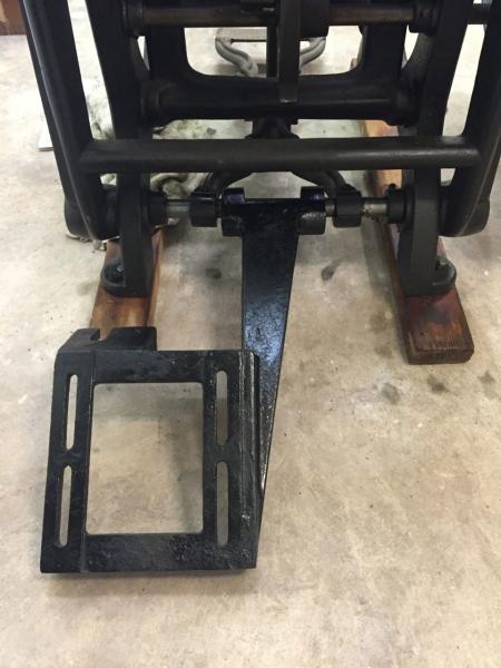
When I purchased the press, it came with a variety of parts for attaching a motor (tight and loose pulleys, shifting lever, fork, etc.). Among these items is a part that the previous owner told me was a motor mount. It is appears to slide over the bed shaft, but I’m not quite sure if I have it oriented correctly.
I’ve spent some time trying to find pictures of a similar installation for reference. Most presses I’ve seen have the motor mounted to a wooden platform that is attached to the skid that the press is sitting on. Does anyone have a picture of a motor installation using this bracket? I’ve attached a picture of my best guess how to install it.
Thanks!
IMG1968.jpg
that looks correct. i’m not sure though if it may slide over to “straddle” the treadle. the motor, shaft, and pulley, stick out from the mount quite a bit. it is very simple in that the weight of the motor is what keeps tension on the belt. the variable speed of the day was a pedestal mounted “resistor box”
That looks to be correct or pretty close. Does the shaft to which the pinion gear is attached stick out far enough to accept the driven pulley? Will you drive with a flat belt or a V-belt? The drive pulley on the motor and the driven pulley outboard of the pinion gear must align. You must also have a proper ratio between the drive pulley and the driven pulley to run the press at a speed that is safe and proper. Typical motors run at 1750RPM. You have to get that down to about 15 (or less)
cycles per minute at the press. I believe the 10 x 15 runs at one cycle per 6 RPM of the main shaft. You either have to have a very large driven pulley, or a two stage speed reduction.
There is an adjusting/tension rod missing that attaches to the left side of the press and rests in the slot on the motor mount on the front left as seen in this picture. There is an attachment for the upper end of the rod that is bolted to the press. The weight of the motor is supported by this arrangement—the motor does not ride free to provide tension. These are usually used in conjunction with a variable speed pulley and a separate base that can be adjusted with a screw mechanism. This was a standard C&P accessory. As presently mounted, it needs to move to the left somewhat so the motor shaft will align with the large pulley depending on how the press is driven. I can take a picture tomorrow.
hmmm… what fritz says sounds correct too. i will check my oldest press tomorrow…
If you have a copy of the classic Western Newspaper Union/Harry W. Brintnall catalog from 1953, the bracket is shown on page 92. My scanner is broken, so can’t scan it.
Attached is a small image of the catalog item to which Fritz referred.
Here’s a link to a temporary copy of a high-res version of the image:
http://galleyrack.com/temp/western-newspaper-union-catalog-53-p092-chand...
Hope this helps.
David M.
www.CircuitousRoot.com
CP Motor Bracket from WNU 53, low-res
I have that mount on my 10x15NS, here it is in action, the mount is about 7 inches off the floor. As you can see from the pictures we had to use angle to get the crown of the old homemade barrel pulley to line up - the pulley on my press shaft sticks way out. Also - the treadle definitely has to come off in order to get the mount over far enough to even be in the neighborhood.
Just put the new endless belt on (so it still needs to be dressed). It runs fast, but not unreasonable.
IMG_0600.JPG
IMG_0599.JPG
IMG_0598.JPG
I think you can’t have both the motor mount and foot treadle on that rear shaft at the same time out of a not enough space question. There is a collar on that shaft that goes up against the motor mount to keep it from wandering.
The WNU 1953 catalog is a gem of information for letterpress. I have my original catalog that they gave me in about 1955, and I have a second copy that I have in the office for reference. These show up on eBay occasionally.
I purchased my 10x15 C&P through WNU in San Francisco back in 1956.
Fritz is, unsurprisingly, correct—you can’t fit both a pulley and motor bracket on this press. At least not with a proper fitment of each.
Brad.
All, this has been very helpful! Especially the photos and scans. Thanks!
To answer the initial questions, I plan to use a variable speed drive with a v-belt pulley, to drive a sheave that will be mounted on the drive shaft.
It’s now clear to me that the treadle needs to be removed to slide the motor mount toward the edge. Doing this will place the motor roughly in line with the shaft where I plan to attach a v-belt pulley. I may need to extend the motor out a little, and the angle-iron method that bstuparyk shows will do the trick. I’ve looked through my various parts and realized that I don’t have the tension bar. I’m not worried about that - should be relatively easy to fabricate something that works.
Having now gone further into the rabbit hole, I’ve realized that I also have the Horton style variable speed pulley. To this point, I didn’t know what to call it. At present, I only have the mount attached, as it serves as a protector for the pinion, but I do have the other parts - I disassembled them when I moved the press.
So upon further inspection, I realized the pulley mount has a place on the back that might be intended for the connection for the tension bar (see red arrows in the pictures). I don’t have any parts that seem to match up to it. Or perhaps the tension bar should be mounted in the hole in the frame (blue arrow). So again, I find myself asking whether anyone has pictures of how this connection works.
P.S. Thanks to David MacMillan, where I found the attached image of the Horton pulley on circuitousroot through diligent google searching for the WNU catalog.
P.P.S. I found a used copy of the Western Newspaper Union catalog on Amazon, it’s already on its way to me. Seems like a great resource! Here’s a link to a couple other copies in case anyone is interested: http://amzn.to/1D9Qo6Z
link-p092-horton-pulley-sf0.jpg
IMG1984.jpg
IMG1982.jpg
IMG1981.jpg
IMG1980.jpg
It’s the hole in the frame indicated by your blue arrow, In my pictures you could have clearly seen that the bracket you have indicated with red arrows is also empty on my press (which also has the Horton Pulley installed) What you are missing in your pictures are a) the rod and b)the bracket that holds the rod on to the press (through the hole indicated by the blue arrow).
The C&P motor bracket is ideally suited to use of the Reeves line of speed control accessories. I have had a Reeves motor mount and variable speed pulley on my 10x15 C&P for the past 60 years. The speed control is set manually for the speed desired, but that’s not much of a chore. I note that they now have a wide belt version of the variable speed pulley available, much like the Heidelberg version. Now knowing this, I may convert my V belt drive to the wide belt version for easier press starting so the belt doesn’t wander off the large press pulley.
See:
http://www.master-pt.com/images/pdf/PULLEY_MPT.pdf
The Reeves adjustable motor base bolts directly to the C&P motor bracket. This item will last a lifetime, as I’m finding out, and will outlast several motors.
I have one of the motor mount shafts excess to my needs should anyone need it.
Thanks all for the additional information! I have never heard of a Reeves pulley and now that I’ve looked it up, I can see its benefits.
I will be sure to update this post when I’ve got it all put together.