Jack-Shaft Install on my C&P OS 10x15
Howdy all and Happy new Year to you.
I recently bought a C&P OS 10x15 which came with a 2HP motor. I am a newbee to all things hands-on about letterpress and thus, I was desperate to find a way to reduce the speed without spending a significant amount of additional money.
With the help of a guy at Grainger who figured the speed of the flywheel (roughly 188rpm) and the reduction (roughly 62rpm) using the jack-shaft, I am at least now willing to give it a try.
Note: I am not electrical-savvy at all but I can build things I understand visually. I got that here at Briar Press from the discussion threads of you fine folks.
Attached image, any thoughts?
Humbly, Tony
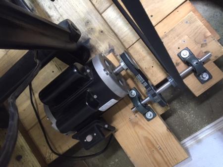
image.jpeg
2 possible options for very little outlay and minimal expertise,!! (a) Nest of 3 or 4 pulley,s facing (mirror image) on the opposing shaft duplicate nest of 3/4 pulleys, belt just flipped over to give 3 or 4 different ratios, as in cycle gear trains, OR (b) just one coned pulley on the driving unit, (motor) to give infinately variable speed range, minature version of Normal/Standard H/berg Platen system. >coned pulley normally sprung loaded and self adjusting< via small arced movement of the motor, not exactly rocket science.??
Seen on B.P. several times fairly recently.!
Your published shot shows plenty of length on both the driver and driven shaft,s for *nest,s of pulley,s* but it would be expedient to place the nest of 3/4 with the larger pulley inboard and next to the bearing of the motor, to keep the Torque and Pressure as close to the bearing as possible,?
The H/berg system usually, has the coned pulley close to the bearing, with the spring mechanism OUTBOARD, of the Cone for this very reason, + the Cone keeps the same attitude and approach of the Belt to the Driven pulley, i.e. the Flywheel of the Platen.
This also applies to the drive train on most small Litho Machines, Multilith Gestalith, Hamada etc.etc.etc
.
As a self proclaimed New devotee, it hopefully follows. that with either of the above systems, as your prowess and speed of feeding increases the speed can be cranked up accordingly, Good Luck.
Thanks Mick/rocket scientist
a couple of explanations:
1) NEST OF PULLEYS: do I use a different belt for each, and slide the shaft left or right to align the desired pulley up to the main motor pulley?
2) Does the angle of the jack-shaft to the motor effect speed?
3) I am not searching with the correct words for “Normal/Standard H/berg Platen” — have a link to a thread on BP?
thanks sir
TG
Thank You, sorry little short on full explanation, only one *V* belt required for the entire Drive train, as the *nest,s of pulley,s* face each other, all that happens is that you flip across as required for the 4 speeds, you effectively reduce on one pulley and increase on the opposite one, merely altering the ratio,s between the Driver & the Driven.
Your shot looks like, at present, slightly smaller Driver with slightly Bigger driven, (on the counter-shaft) which would be logical, i e. more torque and power from the driver, if you go too big with the driving pulley, eventually you over power the driven pulley, especially when driving a secondary pulley to the M/c which again looks as though you are getting substantial reduction to your main drive belt.
With a normal *V* belt as you seem to have on your primary drive, they are usually described as *A* section, i .e. the width and angle of the V proper, in 2 forms either normal V or with gripper teeth incorporated, especially useful when using tiny pulley,s with very little *Wrap Round* and not too much grip.
I and others have posted before, using powdered Rosin to overcome this situation.
Your secondary and main drive belt looks as though it could be *B* section,!! still *VEE* section but wider and deeper, normally used to give more traction onto your Main M/c. pulley.
It may be necessary to involve a simple pair of secondary Feet and or Adjustable rails on the Motor mount to flip the belt over the 3 or 4 options, this has been pictured and posted many times on B.P. with many ingenious and simple options.
Query 2, generally, the speed is only influenced by the Ratio,s of the belt trains (plural) but when any 2 trains of pulley,s are as close as pictured above because there is comparatively little *wrap round* grip is impaired, hence the Toothed belt and Rosin help.
Again apologies re my H/berg similie, there are in B.P. archives and back post,s many exploded diagrams and/or info sheets about H/berg,s drive train.
As I implied crudely, in normal form the motor is mounted on a shaft and platform, with the ability to rise and fall as one, to take up the difference in operating length when increasing or decreasing the Arc of the Motor in relation to the driven flywheel.
The motor remains in the same plane, rarely has to be adjusted laterally, the captive/keyed half of the coned pulley stays in place, the sprung loaded part alters to increase or decrease the ration between driver and driven.
On standard form, the H/B. belt is at least 2” wide and 1/2” thick (metric equivalent) and has *V* section to sit in the Driving pulley, but reverts to flat belt around the Driven pulley. Probably the reason that you MAY find Your secondary belt is *B* section, you may also find that your Driven Pulley, (M/c. flywheel) is slightly CONVEX to keep the belt Running On.
Fairly recently seen on B.P. advice and directives about Taping the Flywheel to create an artificial convex configuration, quick/cheap fix.??
Have also seen, where fixed and free pulley,s are still in place for original line shafting drive, clever use of the Shifter fingers, to act as guides for thin *V* section belts,
Again apologies and good luck. Mick.
Mick, the press came with the motor directly connected via belt to the flywheel … I turned it on and it was rocket fast, I did not get an impression per minute before I installed the jack-shaft.
Now, as pictured, running a 3inch pulley from the motor to a 4inch on the jack-shaft and a 2.5inch pulley on the jack-shaft to the flywheel:
14 impressions per minute, thoughts?
I would like to get it slower than that to start — would simply enlarging the 4inch pulley to a 6inch be significant reduction in speed?
thanks in advance for your time … Tony
Mick,
Heidelberg.
I think it takes more fussing around with the keyboard to produce your abominations—oops, I mean, abbreviations—than it does to type out the full word in a clear and concise manner:
H/Berg
H/B.
H/berg,s
Ugh.
Anyway, back to the topic at hand…
Tony,
You have a 3” pulley on the motor. With a 4” pulley on the jack shaft, you have a 3:4 ratio. Change the 4” jack shaft pulley to a 6” pulley and your ratio becomes 3:6 (1:2). Assuming your 62 RPM number is accurate (I don’t think it is), then the 6” pulley would put you at a final speed of 41 rpm. I think your press makes one impression for 5 revolutions of the flywheel, so 8.2 impressions per minute.
I can provide a clearer breakdown of the whole situation but I need a bit more information:
What is your flywheel diameter?
What is your motor speed?
gentlemen, thanks to you both, very much
flywheel diameter: 39.75 inches
unsure how to determine the motor speed, 2 hp?
also, the flywheel rotates toward the operator, is that correct?
attaching some pics for review:
flywheel39.75inches_X.jpg
motorLabel_x.jpg
pillowblockassemblyJan5_X.jpg
You’ve got the motor speed right on the spec plate. On the left hand side is the “RPM” field. The motor speed is 1755 revolutions per minute.
As to the flywheel rotation direction: the way you have it running now is usually considered incorrect. The press was expected to run the other way. I find this isn’t that much of a problem, however (at least on my New Series Chandler & Price). Mine came from the previous owner already set up to run the “wrong” way and I’ve not changed it yet. After 4 years of light duty in my shop (and probably 50 years of production work at it’s original job) it’s still running fine and hasn’t caused me any problems. I expect yours will be fine the way you have it, as long as it doesn’t bother you.
I do think your final speed is still a bit too high, though, especially for a beginner. I’m generally happy with 8 - 10 impressions per minute. That gives a nice amount of time to make sure the paper has contacted the pins cleanly or to trip the impression if something is wrong while still giving a good production time (480 - 600 impressions an hour). I started at more like half that speed when I was first learning to feed the press. 14 IPM is probably too fast to start with. That’s getting into speeds you could really hurt yourself with. Platen and type are not forgiving to fingers trapped between them!*
You could pretty easily reduce the speed by replacing the final pulley with a smaller one or the large second pulley with a larger one, or both. I think I’d want to take the speed to no more than 8 IPH to begin with.
*The old gent I bought my press from wants to see my fingers every time I see him, just to make sure I haven’t lost any yet!
—
Michael Hurley
Titivilus Press
Memphis, TN
Hey Michael, I appreciate your insight and response as I am looking to get the press running as slow as possible to start with — maybe forever. I have no way to evaluate the run direction as I am just beginning. Hope all is well in Memphis.
The press has Serial Number 04048 which I believe puts it at 1894.
Would you send me a photo of your motor setup?
Tony
oops, checked that SN, it is 04084
Tony
Flywheel rotation on C&Ps has been discussed at length on Briar Press. It was C&P’s specific recommendation that the flywheel rotate away from the operator. The last sentence on this sticker that was on my 10x15 C&P delivery board, circa 1915, states their case:
https://www.flickr.com/photos/53177163@N00/3008271735/in/photolist-6Horz...
thank you Mr Klinke, I will try to get reversing the motor figured out …
Running the press backwards changes the speeds at which the platen swings open and closed. Instead of opening fast and closing slowly, it opens slowly and closes fast. For hand feeding, the latter seems to be more desirable. Reversing your motor should be quite easy, going off of the wiring diagram on the motor. It looks like you’d only need to swap a few connections.
Given the numbers you provided (thanks!) you’re running at 16 impressions per minute.
Possible changes:
(MP = motor pulley, JS = jack shaft input pulley, the 4” one)
MP=1.5”, JS = 6”: 6.6 IPM
MP=1.5”, JS = 4”: 8.3 IPM
MP=2”, JS = 6”: 7.4 IPM
MP=2”, JS = 4”: 11 IPM
MP=3”, JS = 6”: 11 IPM
From what I can tell the direction of the flywheel makes no difference in the opening/closing of the platen. Some presses, like Goldings, do open and close at different speeds based on flywheel direction. Some of the C&P literature I have speaks about the safety of the flywheel rotating away from the operator—it tends to reduce the risk of being pinched by the bull gear on right side of press by feed board.
Brad.
Tony, my press runs via a leather belt from a crowned pulley on the motor output shaft directly to the drive pulley on the right side of my press (opposite the flywheel on the mainshaft). The 1/2HP motor is set up for 800 RPM at 110v/7A and runs through a cheap speed control unit.
This is basically how the press came to me. The only “upgrade” I’ve done so far is to replace the original speed control (which was literally an old wall-mount rotary dimmer switch wired into the power cord!) with a modern cheap control box. It is an improvement, but not by a lot. The photo below was taken shortly after I got the press four years ago and has the old speed control unit visible under the outfeed board.
It runs OK, though the motor doesn’t have quite enough torque down at the slow speeds I want to run it and so I have to keep giving it boosts via a hand on the flywheel. Note that I DO NOT recommend this method, it just happens to be how the press was configured when I got it and I haven’t yet changed it.
Ideally, I’d like to rewire the shed for 240v, set the motor up for split-phase and use a nice solid-state speed controller to make it run all day at any speed I want but that’s going to be down the road a bit (if at all). More realistically, I’d like to put a reduction pulley train in like what you have here to get the speed a bit more manageable and then use the speed control I already have to fine-tune it further.
—
Michael Hurley
Titivilus Press
Memphis, TN
Pressmotorside.jpg
Just wanted to say thanks to everyone. I really try to surround myself with people more talented and smarter than me in hopes of it rubbing off some.
Victory:
original setup:
3 inch motor pulley to 4 inch jack-shaft pulley and a 2.5 inch jack-shaft pulley to the press flywheel = 14 impressions per minute, timed it twice
and now (drum roll please):
modified setup:
3 inch motor pulley to 6 inch jack-shaft pulley and a 2 inch jack-shaft pulley to the press flywheel = 7 impressions per minute!!!!!!!
I will keep my fingers, Lord willing.
Now all I need is to rewire the motor to make the flywheel spin CCW …
jackshaft_setupJan2016.jpg
From your picture, it looks like you have plenty of room to flip the motor around the other way.
Do that and you will be spinning the other direction.