Stuck Throw-Off
Our new (and admittedly still slightly dirty and rusty) C&P New Style 10x15’s throw off won’t budge. I have uploaded pictures of the closed press.
The pin circle and throw-off lever show that the system is nearly half-way thrown off but the location of the eccentric side arm connections seem to indicate that the system is set for impression (such that the side arms as a vector pass through each axis that they are eccentric to when the press is closed— I can’t reason how the back could be pulled any closer for impression than under this condition).
When the “back throw-off connection” between the “slotted piece for throw-off” and the “throw-off saddle” is disconnected, everything from the throw-off lever through to the slotted piece rotates freely so it seems that the problem is the throw-off system being able to rotate the back shaft.
My guess was that the back shaft is either just not loose enough going through the bed or that the relative position of the eccentric side arm connections is incorrect and preventing the back shaft changing them to push the bed away from the platen to throw-off.
The press turns over very easily by hand though, so I think that would rule out the back shaft or side arms being seized themselves. So I am wondering if I need to disconnect the side arms and rotate the back shaft manually to meet the back throw-off connection when the throw-off lever is pulled all the way forward, then turn the press over by hand until the eccentric side arm connections on the platen side are the correct distance from those on the back shaft and finally reinstall the side arms. If I do go through with the second, does the base need to be propped up away from the platen to prevent the side arms from pulling the bed too close during the cycle?
Can anyone verify the relative locations of the pieces shown in the photos? Other explanations for this predicament and ideas for getting out of it are also welcome!
I started a new topic since the other two that I have found…
http://www.briarpress.org/20050
http://www.briarpress.org/6458
…were inconclusive, inactive, and not the exact same press.
Thanks for any help you can give!
Nathan
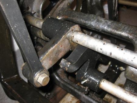
Back Throw-Off Connection, Back Throw-Off Connection, Slotted Piece for Throw-Off, Throw-Off Pin Circle (from left to right)
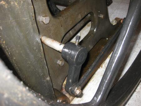
Outer Arm for Throw-Off, Lower Throw-Off Connection (from left to right) (Throw-Off Lever to the right of picture not shown)
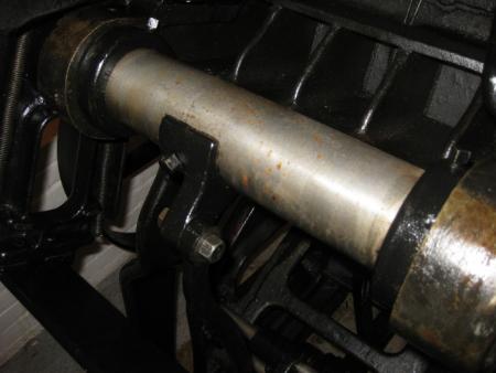
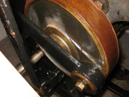
Back Throw-Off Connection, Throw-Off Saddle, Back Shaft (from left to right)
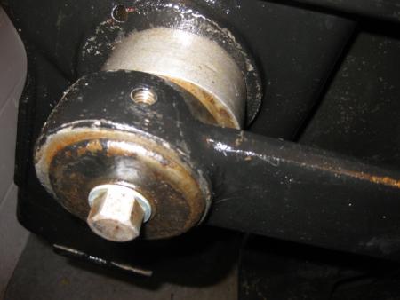
Eccentric connection of Side Arm to Back Shaft
Eccentric connection of Side Arm to Small Head and Lock Cam
In the first picture, what is that nail sticking out of the throw-off pin circle? That looks odd.
Both the circle and the outer arm for throwoff have setcrews which could have loosened, or been tightened in the wrong position.
That is the machine pin that keeps the pin circle locked in place relative to the outer throw-off arm that the throw-off lever connects to via the lower throw-off connection. I needed a new one and couldn’t get an exact diameter with the tools on hand so had a variety of diameters made to use for trial and error. I asked for the pin to be longer than it needed to be to make it easier for me to switch them out during said trial and error process. Once I have everything working, I may remove said pin and have it cut to length— but since it doesn’t interfere with any pieces it is not high on the priority list.
You are correct that both pieces have set screws, but they are both drilled for machine pins as well— so I took that to mean that the set screws were simply used to hold the piece in place while inserting said machine pins since you wouldn’t want just a simple set pin preventing this kind of rotational force without spotting or tapping the shaft.
The machine pins go straight through the cast iron piece and the shaft so can only be used in two positions. I had the pin circle turned the other way but this required that the outer arm be rotated out of the downward position, the position I have seen all outer arms in for impression on C&P’s. Apart from being inconsistent from the diagrams and other examples, turning the outer arm upwards would seem to reduce the mechanical leverage that the throw-off system needs to rotate the back shaft properly.
I don’t see these machine pins specifically called out in the parts list, so it is very possible that these were added later. The possibility exists that they were added slightly off, but I doubt this is the case (or at least I hope not).
I might try removing said machine pin and try rotating it slightly and setting it with the set screw only— but I would think that even if the rotation was off a little bit that it would simply result in the throw-off to position the bed incorrectly rather than not being able to move at all.
At the top of my list is freeing up the back shaft, should it be less than as free to rotate as it should be. Penetrating oil has been suggested to this end, which I will try— but the pieces are not rusted together since they were separate, cleaned, and oiled when I put them together. the one side of the bed was definitely tighter than the other for some reason, which may indeed be the cause of all this.
Nathan
OK, is that a taper pin or a straight pin? I wonder if those fittings are original. I no longer have a C&P to compare.
You mention elsewhere that you had the back shaft out before. Did the problem start before or after that? Could the shaft have been turned end for end? With different orientation of pin holes (if they are tapered), or different wear on shaft and bearings?
You are stuck in the middle of the action, a very curious place to be.
Another thing to check is the throw-off saddle. It can be installed upside down and that slightly alters the geometry. I had this trouble with a throw-off th at wouldn’t switch easily between on and off impression. Turning the saddle around solved it.
The pins are straight pins. I wouldn’t be surprised if they aren’t original— lets hope that whoever modified them had the wherewithal to put them in the right spot.
I wasn’t able to observe the throw-off working before since it wasn’t that whole system wasn’t assembled when we bought it as a restoration project.
I tried rotating the piece with said pin 180 degrees but in order to keep the circle stops around the short throw-off shaft it angled the outer throw-off arm in such a way to nearly defeat the mechanical advantage of the lever and connection trying to turn it. So I am fairly certain that everything is set up correctly in that way.
Regarding the throw-off saddle, flipping it would appear to misalign the piece from the rest of the throw-off linkage. Elsewhere it was suggested that the actual bed shaft could be flipped end to end, which would in turn require the flipping of the saddle in order to line up with the linkage. However, the current configuration is based on the assembled diagrams floating around, which show that the tapping for the saddle is to the left of the center of the back shaft when viewed from the back.
The back shaft and bed casting are currently undergoing a penetrating oil shower and soak. If that does not yield any results before Thursday, when I can finally get some help to remove the back shaft to inspect it and the castings again. The one side of the casting was definitely less than free to rotate when we installed the back shaft, so I am guessing that is the issue now.
Please keep any suggestions coming. I’ll report back what affect the oil has as well as the success of the removal, inspection, and manipulation of the back shaft/bed casting if necessary later this week.
Thanks!
Nathan
You might want to check the level of the press. Make certain the frame isn’t slightly twisted so that there is a binding of the shaft when run through both casting sides.If the press were disassembled and then reassembled on an unlevel floor that could happen quite easily.
I will verify the levelness of the floor and the press itself— I hadn’t paid that too much consideration, but see your point. The bed shaft, a piece that the press was lacking and that I had made, installed without too much trouble— so I would think that any twisting of a frame would have made this an unbearable task since it needed to pass through four castings across two different parts and bear the weight of the bed rather than just passing through the two castings at the top of the bed. Definitely worth checking since it is easy enough to determine and hopefully easier than some other potential problems to remedy. I’ll let you know what I find. Thanks!
Your saddle is different than the one on my 1946 NS C & P.
Mine is an 8 x 12, but the saddles should be the same style. Be that what it may.
There should be a long, slightly S shaped link attached to the saddle. Disconnect the bottom of the link. With any motor belt disconnected, move the link piece up and down essentially along the axis of the link. You are attempting to move/rotate the saddle and thus the shaft attached. A bunch of iron is attached to the shaft so you will be attempting to move all of it. It may take a bit of push-pull, but it should operate smoothly. If it does, your problem is below the link. If it does not move smoothly, your problem is above. Trouble shoot from there, one piece at a time.
Thanks. As stated before, when disconnecting the back throw-off connection, which is the slightly S shaped link, everything from the lever to the slotted piece operates easily. Indeed, as you supposed, the back shaft therefore wouldn’t move with the force that I applied, which is why I was guessing that the back shaft was seized in the bed casting.
My plan to do some investigative disassembly today is going to have to be pushed back since we got a rush order in yesterday. We’ll see what Monday of next week holds for us.
Nathan
What I found out with my 12x18 c&p is just what you have discovered….the back shaft does not rotate freely in the machine casing and side arms. After removing the back shaft completely..which took a lot of work we saw that the shaft had several places where it had become scored or rough (especially where the side arms go.) I gave the shaft a good cleaning and sanded it down with some emory paper try to clean up the rough edges. I also did the same to the inside of the casing and side arms. I lubricated the shaft and casing well before putting it back in. After assembling everything I hardly noticed a change..it was still very hard to move. At that point I regretted not taking it to a machinist to have it cleaned up with the proper tools. In any case I took one of the side arms off again and resanded the end of the shaft and inside the side arm. continuto work the lever back and forth and oiled it as much as possible. It has become better and feels looser I put the side arm back on, and it still feels better. I have connected the motor to it and I will contine to oil it and run it while moving the lever back and forth. I have a feeling it will become free again completely after some use. The machine was in storage for about 10-15 years so I think it was normal that the shaft binded to the casing and side arms.. Good Luck with your machine.
I haven’t been able to try any of what I was planning yet due to being distracted by new projects, sickness, and everything else.
It may be a few weeks until things quiet down enough to go back to trying to get this working.
Sorry to hear that someone else is having a similar problem. I hope it works loose for you. Keep us posted!
Nathan
i don’t see that this machine would “spring” so to speak but if it had possibly been through some extreme temp changes, or bad moving , then “something” could have happened. you need to run the back shaft through, from the op side and make sure it will easily center into the gear side of the bed. then, from the gear side, run the back shaft from the gear side and make sure it easily centers into the op side. It should turn quite freely. the side arms should fit on easily in the “half open” position but take one off and check again in the closed, and open position… several things could be going on here… the side arms need a given amount of “run out” or side to side free play. once installing the backshaft properly,,put only the one end on the backshaft,(open position) the other end needs to be able to overlap and clear the head cam by .010-.030” then do this with the arm on the head cam with relation to the backshaft. use this process on the gear side as well. sounds complicated but really not. if you need more info on this let me know. these machines are just machines and are happy with oil. hope this helps. E ric